
Network maximum flow parallel solving method

A technology of network maximum flow and network flow, which is applied in the field of parallel solution of network maximum flow, can solve problems such as low computing efficiency and insufficient utilization of computing resources, achieve the effect of reducing communication times, meeting software development requirements, and ensuring correctness

Inactive Publication Date: 2013-05-08
吴立新 +1
View PDF2 Cites 6 Cited by
  • Summary
  • Abstract
  • Description
  • Claims
  • Application Information

AI Technical Summary

Problems solved by technology

This method can make full use of single-machine multi-core, multi-machine multi-core and cluster computing hardware and network resources for high-performance computing, and solve bottleneck problems such as low computing efficiency and insufficient utilization of computing resources in traditional serial algorithms.

Method used


Image

  • Network maximum flow parallel solving method
  • Network maximum flow parallel solving method
  • Network maximum flow parallel solving method

Examples


Embodiment Construction

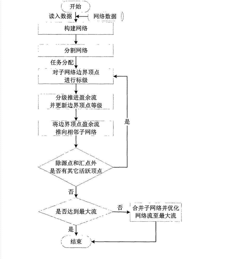
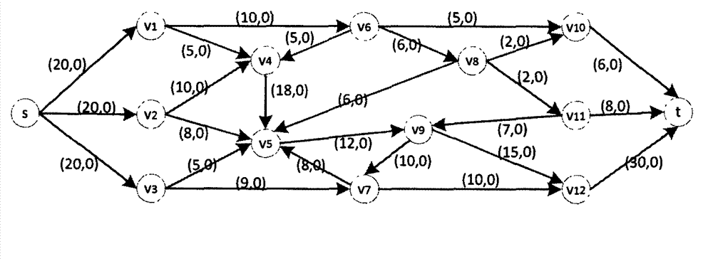
[0051] by figure 2 , image 3 , Figure 4 , Figure 5 , Figure 6 and Figure 7 (in, Figure 2-7 The numbers in square brackets represent capacity and flow respectively, Figure 3-7 The dotted line in the middle is the network dividing line, the arc intersecting the network dividing line is the boundary arc of the sub-network, and the solid line is the arc inside the sub-network, Figure 4-6 The number above or below the middle vertex is the level of the vertex, Figure 7 The dotted line circle is a marked vertex, and the solid line circle is an unmarked vertex) as an example, describe the implementation process of the present invention in detail, and its specific implementation is as follows:

[0052] Step 1: Assume that there are 3 computing units (respectively No. 1, No. 2 and No. 3 computing units), and No. 1 computing unit will figure 2 The network is divided into 3 sub-networks N 1 , N 2 and N 3 (Such as image 3 shown), where d(t, N 3 )>d(t,N 2 )>d(t,N ...


PUM


Abstract

The invention discloses a network maximum flow parallel solving method which comprises the follow steps that 1) network surplus flow is promoted in a parallel iteration mode; and 2) the network flow is optimized in a sub-network merging mode. According to the step 1) of the method, a network is divided into a plurality of sub-networks which are distributed to each computing unit, each computing unit divides border top points into three different levels in a marking mode according to different states of border arcs and border top points of the sub-network of the computing unit, the border top points with different levels push the surplus flow in different modes, pushing efficiency of the surplus flow is guaranteed, communication problems are effectively solved, solving speed of the parallel method is quickened, and meanwhile correctness of results is guaranteed through the step 2).

Description

technical field [0001] The invention relates to a network flow optimization method, in particular to a parallel solution method for the network maximum flow. Background technique [0002] As a classic combinatorial optimization problem, the maximum flow of the network aims to solve the problem of the maximum flow that can be transmitted from the supply point (source point) to the demand point (sink point) in a network with capacity constraints. Engineering fields such as computer networks and scientific fields such as physics and chemistry have a wide range of applications, such as the study of transport capacity in transportation networks, power supply capacity in power supply networks, information transmission capacity in information networks, etc. (RK Ahuja et al., 1993). Solving the network maximum flow problem can give full play to the equipment capabilities of the network and clarify how to transform the network to improve the network transmission capacity. Zhang Xian...

Claims


Application Information

Patent Timeline
Patent Type & Authority Applications(China)
IPC IPC(8): G06Q10/04
Inventor 吴立新江锦成
Owner 吴立新
Learn More