
Bicycle wheel

A technology of bicycles and sprockets, which is applied in the direction of wheels, wheel axle combinations, vehicle components, etc., and can solve problems such as labor

Inactive Publication Date: 2013-05-08
刘俊跃
View PDF0 Cites 5 Cited by
  • Summary
  • Abstract
  • Description
  • Claims
  • Application Information

AI Technical Summary

Problems solved by technology

[0002] Bicycles are the most economical, most environmentally friendly and lightest means of transportation, but riding for a long time will make people feel strenuous. New way to save effort on bicycles

Method used


Image

  • Bicycle wheel
  • Bicycle wheel
  • Bicycle wheel

Examples


Embodiment 1

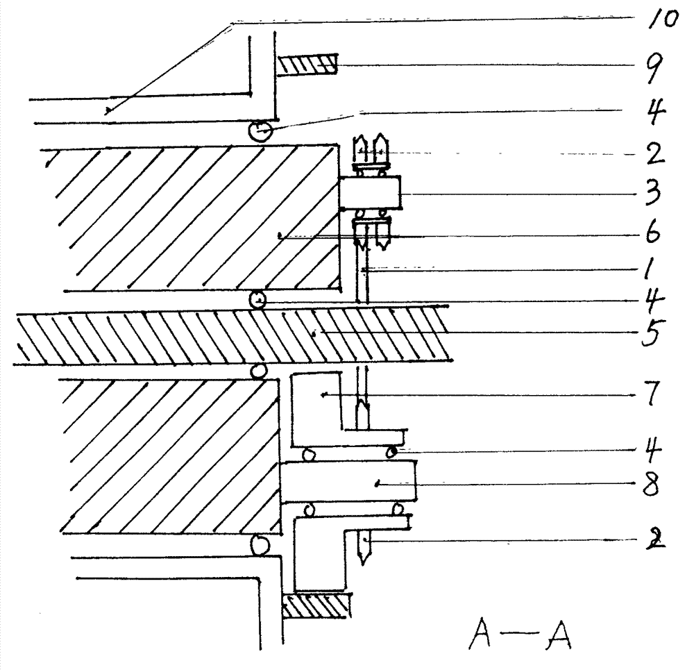
[0014] Embodiment one, combining figure 1 , figure 2 Description: The inner gear ring 9 is installed at the end of the hub 10, and there is a ratchet mechanism between the hub 10 and the inner gear ring 9. A positioning body 6 is installed at the center of the hub 10 , and a bearing 4 is arranged between the positioning body 6 and the hub 10 . The axial centerlines of the four of the wheel, the hub 10, the internal gear ring 9, and the positioning body 6 coincide. The axle shaft 5 is in the middle of the positioning body 6, and the bearing 4 is arranged between the axle shaft 5 and the positioning body 6. Driving gear shaft 8 is at the end of positioning body 6 below, and driving gear shaft 8 is equipped with driving gear 7, and bearing 4 is arranged between driving gear shaft 8 and driving gear 7, and driving gear 7 and internal gear ring 9 are meshed. A sprocket 2 is fixed on the driving gear 7 . The end above the positioning body 6 is equipped with a sprocket shaft 3, ...

Embodiment 2

[0015] Embodiment two, combining image 3 , Figure 4 Description: The inner gear ring 9 is installed in the middle of the hub 10, and there is a ratchet mechanism between the hub 10 and the inner gear ring 9. A sleeve 11 is installed on the inner wall of the hub 10, and a positioning body 6 is installed in the sleeve 11, and a bearing is arranged between the positioning body 6 and the sleeve 11. The axial centerlines of the four of the wheel, the hub 10, the internal gear ring 9, and the positioning body 6 coincide. The axle shaft 5 is at the lower part of the axial centerline of the positioning body 6, and the positioning body 6 has a slot corresponding to the internal gear ring. The driving gear 7 is located at the notch of the positioning body 6 and is installed on the axle 5. A bearing 4 is installed between the driving gear 7 and the axle 5. The driving gear 7 protrudes from the notch of the positioning body 6 and is in phase with the internal gear ring 9. engage. Th...


PUM


Abstract

The invention provides a bicycle wheel. A locating body, an inner gear ring, a driving gear and the like are added to a hub of a driving wheel of a bicycle, and great difference exists between the driving method of the bicycle and an existing transmission method. According to the existing driving method, a chain only drives a fly wheel and the wheels to rotate to enable the bicycle to advance, after the parts are arranged, except that the chain drives a chain wheel namely the fly wheel and the wheels rotate to enable the bicycle to advance, forward inclining force is produced by the wheels, and a labor-saving effect is achieved.

Description

technical field [0001] The invention relates to a bicycle wheel, which is more suitable for bicycle wheels, and its structure is also suitable for motorcycle wheels, electric wheels and the like. Background technique [0002] Bicycles are the most economical, most environmentally friendly and lightest means of transportation, but riding for a long time will make people feel strenuous. New ways to save effort on your bike. Contents of the invention [0003] The solution of the present invention is a bicycle wheel, which is characterized in that: a bearing is installed in the hub, a positioning body is installed in the bearing, and the positioning body is cylindrical and can be hollow. The positioning body middle part is equipped with axle shaft, and bearing is arranged between positioning body and axle shaft, also can have no bearing, but will rotate flexibly. The axial centerline of the positioning body coincides with or is parallel to the axial centerline of the axle. ...

Claims


Application Information

Patent Timeline
Patent Type & Authority Applications(China)
IPC IPC(8): B60B37/00B62M11/02
Inventor 刘俊跃
Owner 刘俊跃
Learn More