
Kitchen waste drying squeezer

A kitchen waste and press technology, which is applied to presses, manufacturing tools, etc., can solve the problems of unsatisfactory processing capacity, high processing cost, time-consuming and labor-intensive extrusion methods, etc., and achieves low processing cost, simple manufacturing process, The effect of increasing the pressing strength

Active Publication Date: 2013-05-08
北京洁绿环境科技股份有限公司
View PDF8 Cites 31 Cited by
  • Summary
  • Abstract
  • Description
  • Claims
  • Application Information

AI Technical Summary

Problems solved by technology

The piston plate of the invention patent application moves periodically on the lead screw, and the piston plate moves from one end of the lead screw to the other end under the drive of the lead screw, and the garbage in the extrusion chamber is squeezed once; the piston plate moves away from the lead screw. The pressure generated at one end of the motor is the largest, thereby squeezing the garbage to remove water; but this kind of extrusion is not continuous, it is intermittent and periodic, and the intermittent periodic extrusion method is time-consuming and laborious, and the amount of rubbish squeezed out per unit time is small , for a treatment plant that treats a large amount of garbage, the processing capacity is far from meeting the requirements; moreover, the electrical control applied for in this invention is complicated, there are many electrical components, and the processing cost is high; in terms of equipment repair and maintenance, the cost is also high; Moreover, the manufacturing and processing are complicated, and the requirements for processing technology and processing materials are high

Method used


Image

  • Kitchen waste drying squeezer

Examples


Embodiment Construction

[0008] The present invention will be described in detail below in conjunction with the accompanying drawings and embodiments.

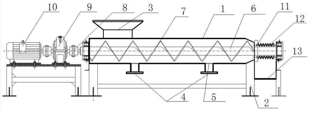
[0009] Such as figure 1 As shown, the present invention includes a squeeze cylinder 1, which is horizontally arranged on the frame 2, one end of the squeeze cylinder 1 as the head end, and a feed port 3 is arranged on the top of the squeeze cylinder 1 near the head end, and the other of the squeeze cylinder 1 One end is used as the tail end, and the tail end is set into a gradually shrinking conical shape. A plurality of water outlets 4 are arranged at intervals at the bottom of the squeeze cylinder 1, and a solid-liquid barrier 5 is arranged on each water outlet 4. A screw shaft 6 is arranged in the axial direction of the squeeze barrel 1, and a screw blade 7 is arranged on the screw shaft 6, and the pitch of the screw blade 7 decreases continuously from the head end to the tail end of the squeeze barrel 1. One end of the screw shaft 6 close to the...


PUM


Abstract

The invention relates to a kitchen waste drying squeezer. The kitchen waste drying squeezer is characterized by comprising a squeezing barrel which is transversely arranged on a frame, wherein the squeezing barrel comprises a head end and a tail end; a feeding hole is formed in the top close to the head end; the tail end is in a cone shape which is gradually shrunk; a plurality of water outlets are formed in the bottom of the squeezing barrel at intervals; a solid-liquid separation fence is arranged on each water outlet; a spiral shaft is axially arranged in the squeezing barrel; spiral blades are arranged on the spiral shaft; the screw pitch of the spiral blades is continuously reduced from the head end to the tail end of the squeezing barrel; one end, which is close to the feeding hole, of the spiral shaft penetrates out of the head end of the squeezing barrel and is connected with a motor through a coupler; the other end of the spiral shaft penetrates out of the tail end of the squeezing barrel and is arranged on the frame; the outer side of the tail end of the squeezing barrel is provided with a baffle; a squeezing spring is arranged on the spiral shaft on the outer side of the baffle; the other end of the squeezing spring is fixed on the frame; and a discharge opening is formed below the squeezing spring. The kitchen waste drying squeezer is simple in structure and low in processing cost and can be widely applied to the kitchen waste treatment process, and moisture in the kitchen waste can be effectively reduced.

Description

technical field [0001] The invention relates to a squeezer for domestic waste, in particular to a squeezer for kitchen waste. Background technique [0002] Kitchen waste is mainly composed of waste generated in the process of kitchen food processing and leftover food on the table (excluding swill), and is a kind of solid waste formed by residents in the process of daily consumption. Kitchen waste has a high water content, high fluidity, and is easy to leak, causing secondary pollution, polluting surface water and groundwater; and a large amount of water in kitchen waste is not conducive to the transportation of waste, let alone incineration of waste. Therefore, it is very important to squeeze, squeeze and dehydrate kitchen waste. [0003] The rubbish squeezing equipment in the prior art has the "restaurant rubbish squeezer" with the invention application number of 200810227550.1. It uses a motor to drive the screw to rotate, and the rotation of the screw generates a torque ...

Claims


Application Information

Patent Timeline
IPC IPC(8): B30B9/14
Inventor 赵凤秋景有海韩创伟张聪慧赵妙田琼琼张玉川张锋董健王方宁
Owner 北京洁绿环境科技股份有限公司
Learn More