Line device for cutting lathe

A technology of routing device and cutting machine tool, applied in the direction of fine working devices, stone processing equipment, manufacturing tools, etc., can solve the problems of high precision requirements, complexity and high cost, and achieve strong anti-interference ability, high operation stability, simple structure

Inactive Publication Date: 2013-05-08
浦学西
View PDF12 Cites 1 Cited by
  • Summary
  • Abstract
  • Description
  • Claims
  • Application Information

AI Technical Summary

Problems solved by technology

[0005] In the actual operation process, as the auxiliary part of the main machine, the diamond wire breakage occurs from time to time due to the change of the electrical control parameters. The wire wheel (heavy weight and high precision requirements) will affect the original accuracy of the machine tool after long-term disassembly and wear, and the wire winding process is more cumbersome and complicated
This structure is not only costly, but the complex structure increases the operational complexity and even instability of the system

Method used


Image

  • Line device for cutting lathe
  • Line device for cutting lathe

Examples


Embodiment Construction

[0016] The present invention will be further described below in combination with specific embodiments.

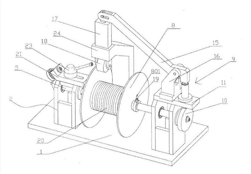
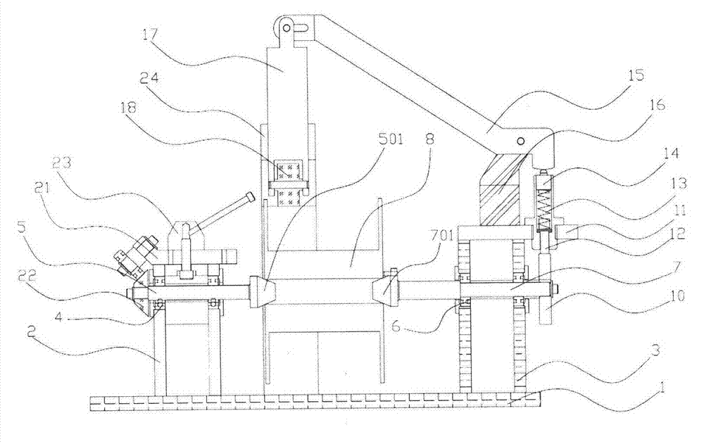
[0017] like figure 1 As shown in FIG. 3 , the wire routing device for a cutting machine tool according to an embodiment of the present invention includes a bottom plate 1 , a first bracket 2 , a second bracket 3 , a first bearing 4 , a first spindle 5 , and a second bearing 6 , the second main shaft 7, the wire wheel 8 and the tension mechanism 9. The tension mechanism 9 includes a friction wheel 10 , a damping bottom plate 11 , a damping rod 12 , a spring 13 , a pressing shaft 14 , a lever 15 , a lever bracket 16 , a slide bar 17 and a nylon wheel 18 .

[0018] The first bracket 2 and the second bracket 3 are fixedly connected to the base plate 1 by screws. The first bearing 4 is fixedly connected to the first bracket 2 . The first main shaft 5 is mounted on the first bearing 4 . The second bearing 6 is fixedly connected to the second bracket 3 . The second main shaft...


PUM


Abstract

The invention discloses a line device of a cutting lathe. The line device of the cutting lathe comprises a base plate, a first support frame, a second support frame, a first bearing, a first main shaft, a second bearing, a second main shaft, a line wheel and a tension mechanism. The first support frame and the second support frame are fixedly connected on the base plate. The first bearing is fixedly connected on the first support frame. The first main shaft is arranged on the first bearing and the second bearing is fixedly connected on the second support frame. The second main shaft is arranged on the second bearing. The line wheel is arranged between the first main shaft and the second main shaft. One end of the second main shaft is provided with a transmission hook. A first through hole is arranged in the line wheel and the transmission hook hooks the first through hole. The tension mechanism is fixedly connected on the base plate. The line device of the cutting lathe is simple in structure, capable of rapidly coiling, convenient to operate, stable in tension as the tension mechanism is used, high in stability of operation of the device and high in anti-interference ability.

Description

technical field [0001] The invention belongs to the field of cutting machine tool equipment, and more specifically relates to a wire routing device for a cutting machine tool. Background technique [0002] With the vigorous development of the photovoltaic industry abroad, silicon chips are widely used in the photovoltaic industry, and the demand for silicon chips has also greatly increased. In 2009, the first silicon core cutting machine tool developed by an American company came out. It adopts advanced mechanical structure and order control and winding methods, and cuts silicon rods through diamond wires. In terms of silicon core cutting technology in the photovoltaic industry at home and abroad, occupies an absolute dominant position. [0003] In 2010, the domestic photovoltaic industry also began to develop rapidly, which led to an increase in the demand for silicon core cutting machine tools. The silicon core cutting machine tool uses a special diamond wire to form a c...

Claims


Application Information

Patent Timeline
Patent Type & Authority Applications(China)
IPC IPC(8): B28D5/04
Inventor 浦学西
Owner 浦学西
Why Eureka
Try Eureka