Turbine Rotor Vehicle Fixture

A technology for turbine rotors and vehicles, which is applied in clamping, manufacturing tools, supports, etc., and can solve problems that affect the quality of center hole processing

Inactive Publication Date: 2015-07-29
WUXI MINGZHU TURBOCHARGER MFG
View PDF4 Cites 0 Cited by
  • Summary
  • Abstract
  • Description
  • Claims
  • Application Information

AI Technical Summary

Problems solved by technology

[0002] After the friction welding of the turbine rotor, the two ends of the turbine rotor need to be machined with center holes. Since the contour surface of the rotor disc has a certain slope, if it is fixed with an ordinary three-jaw chuck, it cannot ensure that the end faces of the two ends of the turbine rotor are perpendicular to the axis of the lathe. Thus affecting the machining quality of the center hole

Method used


Image

  • Turbine Rotor Vehicle Fixture
  • Turbine Rotor Vehicle Fixture
  • Turbine Rotor Vehicle Fixture

Examples


Embodiment Construction

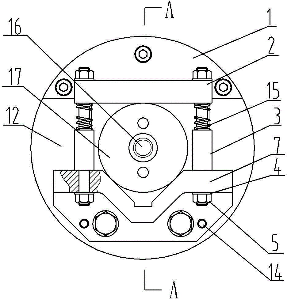
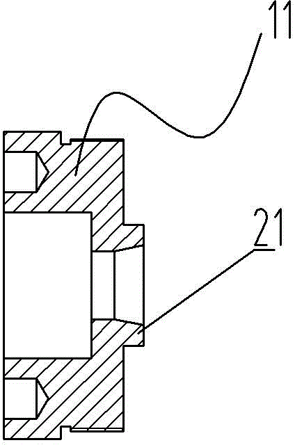
[0016] See Figure 1 to Figure 5 , a fixture for a turbine rotor vehicle, which includes a chassis 12 and a counterweight 1, the counterweight 1 is mounted on the edge of the chassis 12 through bolts, and includes a positioning device, the positioning device includes a positioning sleeve 6 and a centering nut 11, and the centering nut 11 Vertically installed in the center of the chassis 12 and fastened with bolts, the top of the centering nut 11 is provided with a positioning ring, the positioning sleeve 6 is installed on the outside of the centering nut 11, and is threaded with it, and one end of the positioning sleeve 6 is rigidly connected with a balance plate 17, to be processed The turbine rotor 16 is installed in the positioning sleeve 6, its shorter shaft end is fixed in the centering nut positioning ring 21, and its long shaft end is pressed by the balance plate 17; it also includes a clamping device, and the two sides of the positioning device are clamped The device i...


PUM


Abstract

The invention provides a clamp for lathing a turbine rotor. The clamp can fixedly clamp the turbine rotor to be machined to ensure that end faces of two ends of the turbine rotor to be machined are perpendicular to a lathe axis and ensure the machining quality of a central hole of the turbine rotor. The clamp comprises a base plate and a balancing weight, wherein the balancing weight is arranged on the edge of the base plate by a bolt. The clamp is characterized by comprising a positioning device; the positioning device comprises a positioning sleeve and a centering nut; the centering nut is vertically arranged in the center of the base plate and is fastened by using the bolt; a positioning ring is arranged on the top of the centering nut; the positioning sleeve is arranged outside the centering nut and is in threaded connection with the centering nut; one end of the positioning sleeve is in rigid connection with a balance plate; the turbine rotor to be machined is arranged in the positioning sleeve; and the short shaft end of the turbine rotor to be machined is fixed in the positioning ring of the centering nut, and the long shaft end of the turbine rotor to be machined is compacted by the balance plate.

Description

technical field [0001] The invention relates to the technical field of processing tooling for parts of an automobile supercharger system, in particular to a fixture for a turbine rotor vehicle. Background technique [0002] After the friction welding of the turbine rotor, the two ends of the turbine rotor need to be machined with center holes. Since the contour surface of the rotor disc has a certain slope, if it is fixed with an ordinary three-jaw chuck, it cannot ensure that the end faces of the two ends of the turbine rotor are perpendicular to the axis of the lathe. Thus affecting the machining quality of the center hole. Contents of the invention [0003] In view of the above problems, the present invention provides a fixture for a turbine rotor, which can fix and compress the turbine rotor to be processed to ensure that its two end faces are perpendicular to the axis of the lathe and ensure the machining quality of the center hole of the turbine rotor. [0004] Its ...

Claims


Application Information

Patent Timeline
Patent Type & Authority Patents(China)
IPC IPC(8): B23Q3/00
Inventor 薛谷啸
Owner WUXI MINGZHU TURBOCHARGER MFG
Why Eureka
Try Eureka