
High-speed circular sawing machine

A circular sawing machine, high-speed technology, applied in sawing machine devices, metal sawing equipment, metal processing equipment and other directions, can solve the problems of insufficient clamping mechanism feeding mechanism, difficult high-speed precision cutting, slow cutting speed, etc. Achieve the effect of simple structure, labor saving and fast cutting speed

Inactive Publication Date: 2013-05-08
HANGZHOU TIANHE COMP NETWORK CO LTD
View PDF6 Cites 9 Cited by
  • Summary
  • Abstract
  • Description
  • Claims
  • Application Information

AI Technical Summary

Problems solved by technology

[0002] At present, the existing metal cutting equipment is mainly ordinary sawing machine or ordinary metal circular sawing machine. The efficiency is relatively low, especially when cutting metal pipe fittings with high hardness such as alloys, the cutting efficiency is lower, and the cutting speed of the equipment is also low, and domestic improvements have been made to the equipment in response to these problems, such as China No. ZL2004200478012 Patent No. 1 discloses a full-automatic metal circular saw machine. The structure of this equipment is relatively complicated, and the clamping mechanism A and the feeding mechanism are not perfect enough, and the energy consumption is also high; the stability of the operation of the whole machine is low. , the operation is cumbersome, and the cutting speed is slow. When cutting carbon steel, alloy steel and other metals, it is difficult to achieve effective high-speed precision cutting

Method used


Image

  • High-speed circular sawing machine
  • High-speed circular sawing machine
  • High-speed circular sawing machine

Examples


Embodiment Construction

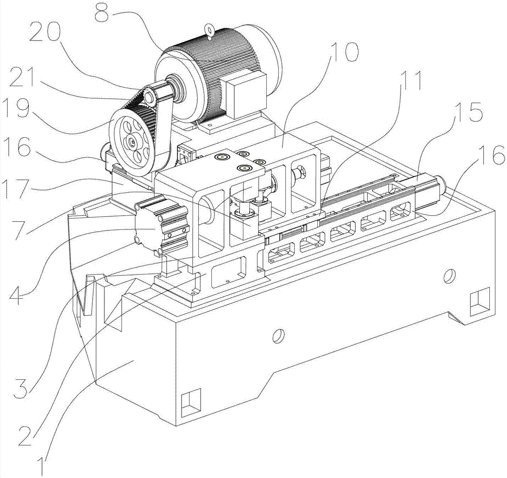
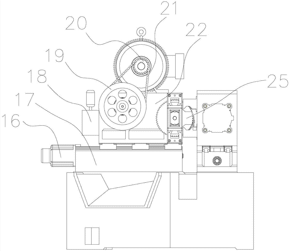
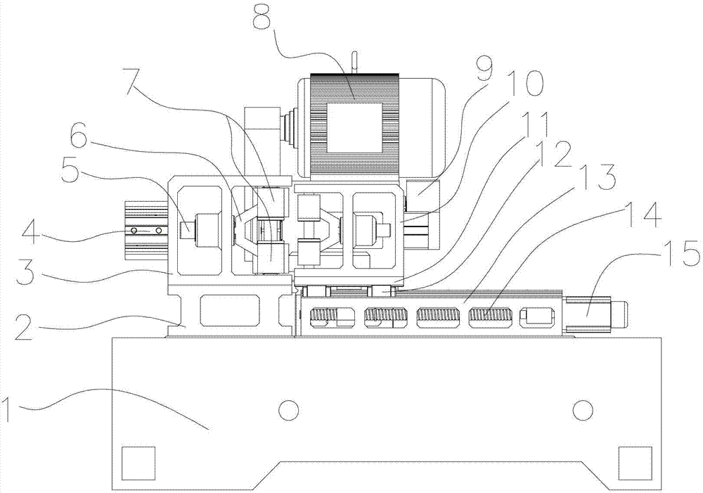
[0020] Referring to the accompanying drawings: a high-speed circular saw machine includes a bed, one end of the bed is provided with a top double-clamp clamping mechanism A and a parallel cutting mechanism, and the other end is provided with a feeding mechanism. Mechanism A includes a front clamping base installed on the bed. A clamping mechanism B with an opening at one end is provided on the front clamping base. One side of the clamping mechanism B is fixedly connected with a cylinder; the parallel cutting mechanism includes There is a cutting base arranged on the bed, and a linear guide rail is provided on the cutting base. A feed motor B is installed on one side of the cutting base, and a screw B is installed on the output end of the feed motor B. The linear guide rail A linear guide rail slider is slidably installed on the screw rod B, and a screw nut fixing block is installed on the screw rod B. The linear guide rail slider is driven by the screw rod B, and a spindle box ...


PUM


Abstract

The invention discloses a high-speed circular sawing machine which comprises a lathe bed. A top double-clamping clamping mechanism and a parallel cutting mechanism are arranged at one end of the lathe bed, and a feeding mechanism is arranged at the other end of the lathe bed. The top double-clamping clamping mechanism comprises a front clamping base installed on the lathe bed, and the front clamping base is provided with a clamping frame with an opening arranged at one end. The high-speed circular sawing machine is simple in structure, convenient to install, strong in stability, high in automation degree, high in the running efficiency of the whole machine, low in energy consumption, simple to operate, and fast in cutting speed, and can save labor, and meanwhile high-speed precise cutting off of carbon steel and alloy steel and the like can be carried out, service life of a blade is prolonged, automatic continuous feeding is achieved, clamping efficiency is high, performance is stable, the service lives of main components of the device are improved, the benefit of an enterprise is increased, and labor intensity is reduced.

Description

Technical field: [0001] The invention relates to a metal circular saw machine, in particular to a high-speed circular saw machine used for high-speed and precise cutting of carbon steel and alloy steel. Background technique: [0002] At present, the existing metal cutting equipment is mainly ordinary sawing machine or ordinary metal circular sawing machine. The efficiency is relatively low, especially when cutting metal pipe fittings with high hardness such as alloys, the cutting efficiency is lower, and the cutting speed of the equipment is also low, and domestic improvements have been made to the equipment in response to these problems, such as China No. ZL2004200478012 Patent No. 1 discloses a full-automatic metal circular saw machine. The structure of this equipment is relatively complicated, and the clamping mechanism A and the feeding mechanism are not perfect enough, and the energy consumption is also high; the stability of the operation of the whole machine is low. ...

Claims


Application Information

Patent Timeline
Patent Type & Authority Applications(China)
IPC IPC(8): B23D47/08B23D47/12B23D47/04
Inventor 王哲平
Owner HANGZHOU TIANHE COMP NETWORK CO LTD
Learn More