Liquid filter

A liquid filter and filter element technology, which is applied in the direction of gravity filter, chemical instrument and method, semi-permeable membrane separation, etc., can solve the problems of uneven pore size, unsuitable filter, high production cost, etc.

Inactive Publication Date: 2013-05-08
刘子渊
View PDF7 Cites 1 Cited by
  • Summary
  • Abstract
  • Description
  • Claims
  • Application Information

AI Technical Summary

Problems solved by technology

This flat filter has four defects. One is that when the filter membrane is fixed with a fixing ring, the surrounding area of ​​the filter membrane must be evenly coated with colloid, and then pasted on the fixing ring. In addition, the processed filter must be sterilized at 60-70°C before leaving the factory, and the colloid will be partially melted at high temperature, and there will be quality problems of poor sealing; the second is that this filter has a filter membrane , there are fixed rings, upper and lower end caps, the structure is complex, not only the production cost is high, but also each process may cause quality problems to the filter; the third is that the particles in the liquid are in a relatively static state, not only has a certain restriction on the flow rate , and it is easy to block the filter membrane; in addition, the utilization efficiency of the filter membrane is low. In order to meet the flow requirements, the volume of the filter is usually large
In addition, most of the filter membranes currently used are nuclear pore membranes produced on reactors. The pore size is uneven, and some radioactive pollution remains. It is not suitable for making medical infusion set filters.

Method used


Image

  • Liquid filter
  • Liquid filter

Examples


Embodiment 1

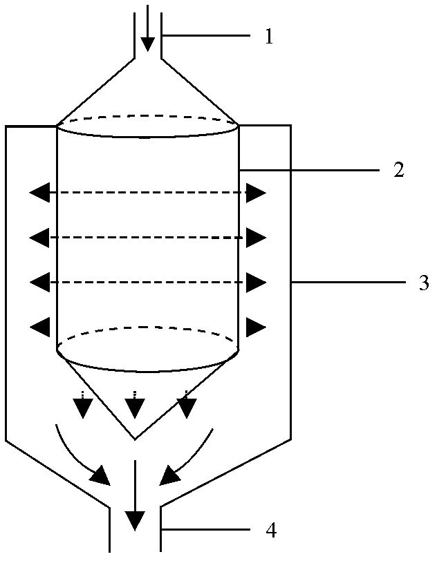
[0019] like figure 1 As shown, a liquid filter includes a filtrate collector 3 and a nuclear pore membrane filter element 2 . The middle part of the filtrate collector 3 is cylindrical, and the upper and lower parts are conical at the top, wherein the upper part is cross-linked with the liquid inlet pipe 1, and the bottom is cross-linked with the liquid outlet pipe 4. The nuclear pore membrane filter element 2 made of the heavy ion microporous filter membrane produced by the accelerator is arranged in the filtrate collector 1. The nuclear pore membrane filter element 2 is processed by a rectangular filter membrane, and the two sides are cross-linked so that the middle part is cylindrical. The upper part is connected with the liquid inlet pipe 1 through cross-linking, and the bottom part is cross-linked into a wedge shape to seal the bottom.

[0020] Among them, the nuclear pore membrane filter element 2 uses a transparent plastic film with a thickness of 5-50 microns as the b...

Embodiment 2

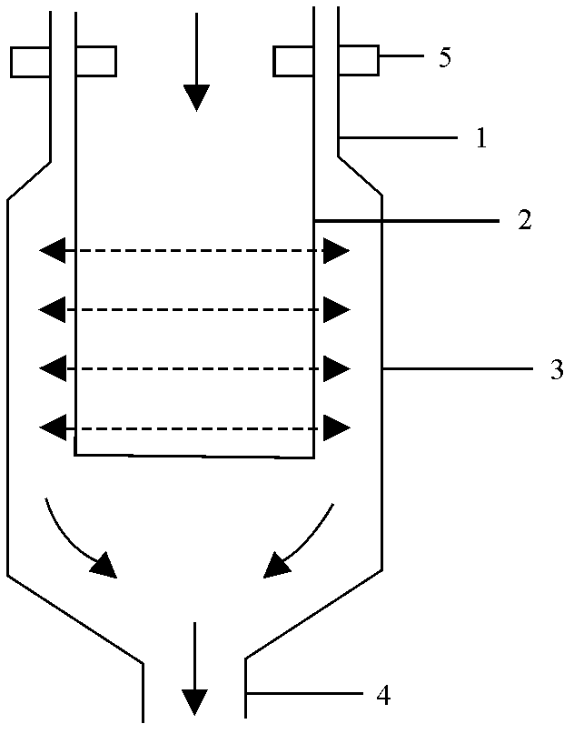
[0022] Like the liquid filter structure described in Embodiment 1, the difference is that, as figure 2 As shown, the liquid inlet pipe 1 and the liquid collector 3 are integrated, and the top of the nuclear pore membrane filter element 2 is directly cross-linked with the liquid inlet pipe 1 .

Embodiment 3

[0024] Like the liquid filter structure described in Embodiment 2, the difference is that, as figure 2 As shown, after the upper side of the nuclear pore membrane filter element 2 is cross-linked with the liquid inlet pipe 1, it is fixed with the clamp 5 again.


PUM

PropertyMeasurementUnit
Thicknessaaaaaaaaaa
Apertureaaaaaaaaaa
Thicknessaaaaaaaaaa

Abstract

The invention discloses a liquid filter manufactured by using liquid column fluidics technology. The liquid filter comprises a filtrate collector, and a nuclear track membrane filter core; a liquid inlet pipe is disposed at the top of the filtrate collector, and a liquid outlet pipe is disposed at the bottom; the nuclear track membrane filter core is disposed in the filtrate collector. The nuclear track membrane is in a bag form, is connected with the liquid inlet pipe at the upper part, and has a flat, conical, semispherical or wedge-shaped bottom. The liquid filter is simple in structure and easy to machine; the filtration efficiency is high; the filter core is not easy to obstruct; and the service life is long.

Description

technical field [0001] The invention belongs to the technical field of filters, and in particular relates to a liquid filter made by applying liquid column jet technology. Background technique [0002] When people need to filter the sundries in the liquid, they usually choose a sieve whose pore size is smaller than the grain size of the sundries, and place the sieve at the bottom of the container to make a filter. There are three main types of filter membranes used for debris filtration: plastic fiber membranes, nuclear pore membranes generated by fission fragments produced by reactor neutrons hitting uranium targets, and heavy ion microporous membranes generated by heavy ions accelerated by accelerators , the latter two are nuclear pore membranes. The microporous structure of the plastic fiber membrane is a labyrinth structure composed of many slits. There is no single pore size, so there is no strict interception threshold. The size of the trapped particles has a statisti...

Claims


Application Information

Patent Timeline
IPC IPC(8): B01D29/27B01D63/10
Inventor 刘子渊
Owner 刘子渊
Why Eureka
Try Eureka