Trajectory control device
A trajectory control and trajectory technology, applied in the field of trajectory control devices, can solve the problems of insufficient correction of trajectory errors and trajectory errors, and achieve the effects of improving trajectory accuracy, suppressing trajectory errors, and improving the quality of machined surfaces.
- Summary
- Abstract
- Description
- Claims
- Application Information
AI Technical Summary
Problems solved by technology
Method used
Image
Examples
Embodiment approach 1
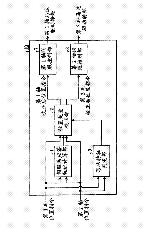
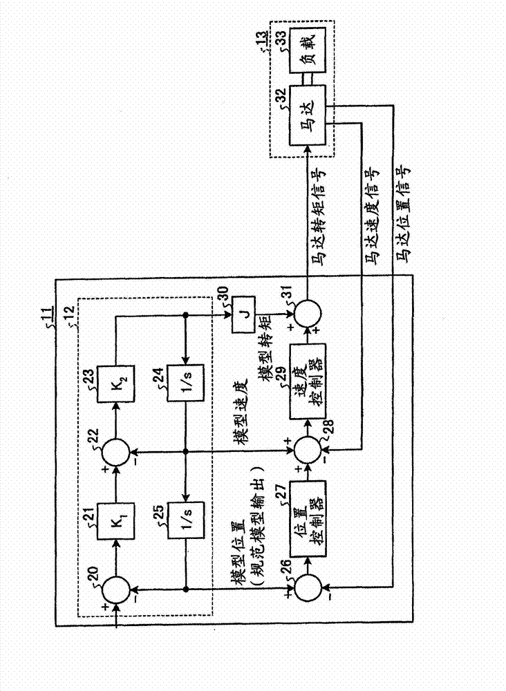
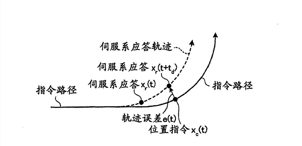
[0027] figure 1 It is a block diagram showing Embodiment 1 of the trajectory control device of the present invention. The trajectory control device 10 is configured to include a servo system response trajectory calculation unit 1 , a shape characteristic determination unit 9 , a position vector correction unit 2 , a first axis servo control unit 7 , and a second axis servo control unit 8 . The command path of the tool (blade object) is provided as the position command of the first axis and the second axis of the machine in the form of an NC program or the like. The servo system response trajectory calculation unit 1 calculates the response trajectory of the servo system when the first axis position command and the second axis position command are given. The calculation method of this response trajectory will be described later. The shape feature determination unit 9 determines whether the command path determined by the first axis and second axis position commands is a straig...
Embodiment approach 2
[0079] The structure of embodiment 2 is roughly the same as that of embodiment 1, and its structure is as follows figure 1 shown. The difference from the first embodiment is the method of determining the reference point and the correction vector in the correction vector calculation unit 3 . These differences will be described below.
[0080] The operation of the servo system response trajectory calculation unit 1 is the same as that of the first embodiment. In addition, in the operation of the position vector correcting unit 2 , the calculation of the trajectory error is the same as that of the first embodiment. Figure 7 It is a diagram showing the operation of the shape characteristic determination unit 9 according to the second embodiment. In this embodiment, the operation in the case of shifting from a circular arc to a straight line is assumed. Therefore, as the shape feature quantity (boundary point coordinates), the coordinate value of the junction of the arc and th...
Embodiment approach 3
[0089] The structure of embodiment 3 is roughly the same as that of embodiment 2, and its overall structure is as follows figure 1 shown. The difference from Embodiment 2 is the operation of the servo system response trajectory calculation unit. In addition, as the shape of the command path, consecutive circular arc commands with different orientations are given.
[0090] Figure 9 It is a figure explaining the operation|movement of the servo system response trajectory calculation part 1 in this Embodiment 3. In Embodiment 3, the response trajectory of the servo system is not obtained using a model of the servo system, but is obtained using only position command information. When the command shape is a smoothly changing shape such as an arc, there is a property that a trajectory error occurs in the acceleration direction of the command path in proportion to the magnitude of the acceleration. This proportionality factor is determined by the responsiveness of the servo syste...
PUM
 Abstract
Description
Claims
Application Information
 - R&D
- Intellectual Property
- Life Sciences
- Materials
- Tech Scout
- Unparalleled Data Quality
- Higher Quality Content
- 60% Fewer Hallucinations
Browse by: Latest US Patents, China's latest patents, Technical Efficacy Thesaurus, Application Domain, Technology Topic, Popular Technical Reports.
© 2025 PatSnap. All rights reserved.Legal|Privacy policy|Modern Slavery Act Transparency Statement|Sitemap|About US| Contact US: help@patsnap.com


