Bearing housing for exhaust turbocharger

A bearing housing, exhaust turbine technology, applied in the direction of rotating bearings, bearings, bearing assembly, etc., can solve problems such as damage to the system and hinder the assembly of speed sensors

Inactive Publication Date: 2015-08-12
BORGWARNER INC
View PDF8 Cites 0 Cited by
  • Summary
  • Abstract
  • Description
  • Claims
  • Application Information

AI Technical Summary

Problems solved by technology

If the rotational speed sensor has to be replaced during maintenance, the spacer can rotate and thereby hinder the assembly of the rotational speed sensor, or even damage the entire system

Method used


Image

  • Bearing housing for exhaust turbocharger
  • Bearing housing for exhaust turbocharger
  • Bearing housing for exhaust turbocharger

Examples


Embodiment Construction

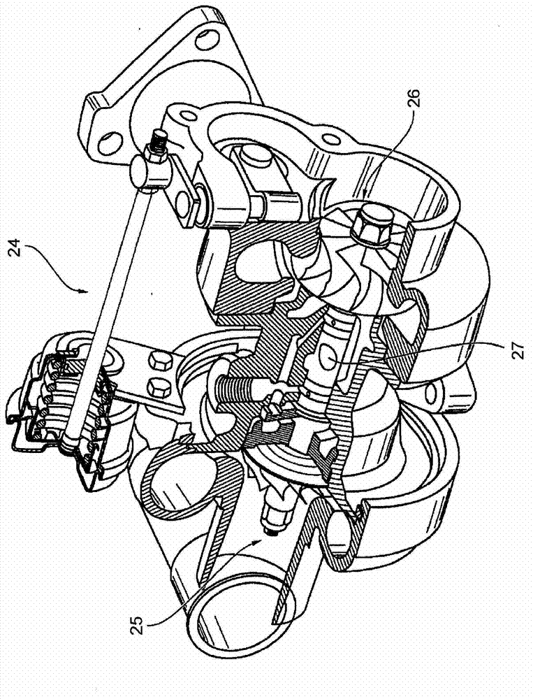
[0014] figure 1 An exhaust-gas turbocharger 24 according to the invention is shown having a turbine 26 and a compressor 25 which are connected to one another via a bearing housing 1 in which a shaft 27 is mounted. It is self-evident that the exhaust-gas turbocharger 24 also has all other conventional components, but these will not be described in detail, since they are not required for explaining the principles of the invention.

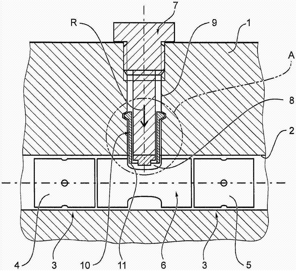
[0015] figure 2 A portion of the inventive bearing housing 1 of the turbocharger 24 is shown. The bearing housing 1 has a mounting hole 2 in which a bearing arrangement 3 for the shaft 27 is arranged. The bearing arrangement 3 has two bearing bushes 4 and 5 arranged in the mounting hole 2, and a spacer 6 is arranged between these bearing bushes,

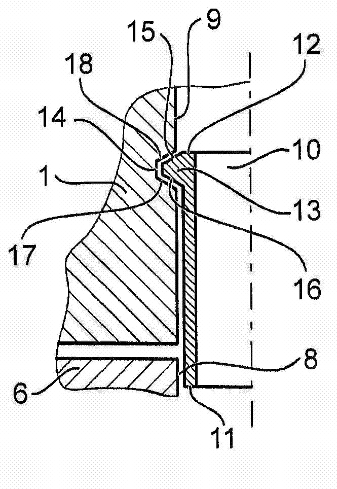
[0016] according to figure 2 The bearing housing 1 also has a rotational speed sensor 7 . The rotational speed sensor 7 is fastened (for example screwed) in the bearing housing recess 9 . Furthermor...


PUM


Abstract

A bearing housing (1) of an exhaust-gas turbocharger (24), having a mounting bore (2), a bearing device (3) which has two bearing bushes (4, 5) arranged in the mounting bore (2), between which bearing bushes is arranged a spacer (6), and a rotational speed sensor (7) which is fixed in a bearing housing recess (9) and which engages into a sensor recess (8) of the spacer (6). A resilient sleeve (10) is arranged in the bearing housing recess (9) around the rotational speed sensor (7) and engages with one end (11) into the sensor recess (8).

Description

technical field [0001] The invention relates to a bearing housing of an exhaust gas turbocharger, which has a mounting hole, a bearing arrangement and a rotational speed sensor, said bearing arrangement having two bearing bushes arranged in said mounting hole, in A spacer is arranged between the bearing bushes, the rotational speed sensor is fixed in a bearing housing recess, and the rotational speed sensor engages in a sensor recess of the spacer. Background technique [0002] A generic bearing housing has a mounting opening in which a bearing arrangement for mounting a shaft of an exhaust-gas turbocharger is arranged. The bearing arrangement has two bearing bushes whose distance from one another is determined by a spacer arranged between the bearing bushes. Furthermore, the bearing housing has a rotational speed sensor which is fastened in a bearing housing recess and which engages in a sensor recess of the spacer, since the rotational speed sensor must be directed toward...

Claims


Application Information

Patent Timeline
Patent Type & Authority Patents(China)
IPC IPC(8): F02B39/00F01D25/24F01D25/16
CPCF01D25/24F01D17/06F16C2360/24F16C35/02F05D2220/40F01D25/16F16C17/18F16C17/02F16C41/00F16C2226/50F02B39/00
Inventor J·霍恩巴赫
Owner BORGWARNER INC
Why Eureka
Try Eureka