
A construction method and device for a gate slot

A technology of construction device and door slot, which is applied in marine engineering, water conservancy engineering, hydroelectric power station, etc., can solve the problems of water leakage, slow construction progress, and large input of human and material resources.

Active Publication Date: 2017-04-12
CHENGDU ALANGTECH
View PDF5 Cites 0 Cited by
  • Summary
  • Abstract
  • Description
  • Claims
  • Application Information

AI Technical Summary

Problems solved by technology

Because most water conservancy and hydropower projects now use large-area steel formwork for rapid concrete construction, the disadvantage of the second-phase installation method of the door slot is that due to the small working space, there is currently a lack of effective mechanical means to assist construction, which not only leads to the construction progress The problem of slowness, safety hazards caused by high-altitude operations are unavoidable, and water leakage often occurs due to the poor quality of the bonding surface between the first-stage and second-stage concrete
In order to optimize the construction, a method of installing the door slot with concrete in the first stage was produced, such as adding support materials to the door slot for reinforcement in the first phase, and using the gate body as a support to install the door slot, etc., because the embedded structure of the door slot, Installation quality requirements and the relationship with related concrete pouring construction require a large investment in manpower and material resources on site, and cannot achieve mechanized and efficient operations comparable to concrete pouring. Previously, it was only used in small-sized door slots

Method used


Image

  • A construction method and device for a gate slot
  • A construction method and device for a gate slot
  • A construction method and device for a gate slot

Examples


Embodiment 1

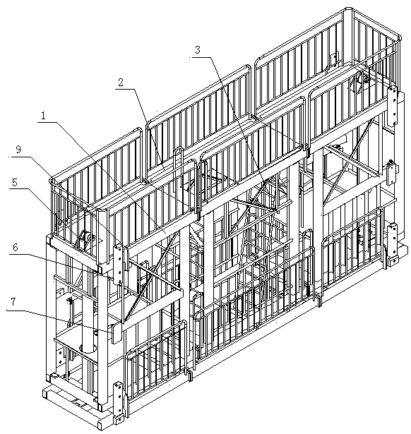
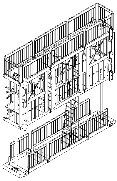
[0029] Embodiment 1: construction method such as flow process figure 1 as shown in figure 2 , 3 , the planar gate slot construction device shown in 4 and Figure 5 In the shown gate slot, after the gate slot bottom plane is poured and formed, the gate slot construction device is installed at the predetermined position according to the design and measurement. The truss structure (1) is within the installation area of ​​the four plane door slots (8) on the same plane, and after the levelness and verticality of the truss structure (1) meet the installation accuracy requirements of the door slots, the four plane door slots (8 ) is connected with the truss structure (1) through a positioning device (6), the adjustment device (9) on the truss structure (1) is used for adjusting the position of the center line of the door slot, and the top of the truss structure (1) has a screw rod (11) Or bolts to adjust the structure to ensure that the door slots do not twist. When the centerli...

Embodiment 2

[0031] Embodiment 2: The construction method of door slot such as process figure 2 as shown in Figure 5For the gate slot of the planar gate shown, two winches (13) and fixed brackets (14) are arranged on the top of the gate slot. After the plane pouring is formed at the bottom of the gate slot, the gate slot construction device is installed at the predetermined position according to the design and measurement. The truss structure (1) is located in the installation area of ​​the four door slots on the same plane. After the levelness and verticality of the truss structure (1) meet the installation accuracy requirements of the door slots, the four plane door slots (8) and the truss structure (1) Connected by the positioning device (6), the adjustment device (9) on the truss structure (1) is used to adjust the position of the center line of the door slot, and the top of the truss structure (1) has a screw (10) or bolt adjustment structure , to ensure that the plane door slots (...

Embodiment 3

[0033] Embodiment 3: The construction method of the door slot such as flow process figure 1 shown, as Figure 5 As shown in the planar gate slot, a fixed bracket (14) or a fixed anchor point is set on the top, and a steel strand climber is installed on the set lifting point. Install the door slot construction device. The truss structure (1) is within the installation area of ​​the four plane door slots (8) on the same plane, and after the levelness and verticality of the truss structure (1) meet the installation accuracy requirements of the door slots, the four plane door slots (8 ) is connected with the truss structure (1) through a positioning device (6), the adjustment device (9) on the truss structure (1) is used for adjusting the position of the center line of the door slot, and the top of the truss structure (1) has a screw rod (10) Or adjust the structure with bolts to ensure that the plane door slots (8) do not twist. When the centerline position and verticality of t...


PUM


Abstract

The invention designs a gate slot construction device, which is used for realizing rapid gate slot construction of a gate by adopting a mechanical process. The device is provided with a gate slot positioning and clamping mechanism and a steel template, wherein left and right side members of each section of gate slot are connected with a climbing mechanism; after a gate slot is arranged, the lower end of the gate slot is kept fixed; a gate slot pouring space is closed by using the steel template, and concrete is poured; and the gate slot climbing device climbs by one section after one layer of concrete is poured every time. A truss structure in a novel gate slot construction device for the gate has the characteristics of high overall rigidity, high reliability and generality in a certain size range, so that the conventional open air dangerous operation way is turned into a way which is centered by highly mechanical assembly operation and assisted by manual operation, the construction safety and quality of a gate slot for a planar gate or an arc-shaped gate are guaranteed easily, and maximization of an engineering economic value is realized through a rapid construction way.

Description

technical field [0001] The invention belongs to the field of water conservancy and hydropower engineering construction, and relates to a method and a device for installing gate grooves and rapid concrete construction. Background technique [0002] In water conservancy and hydropower projects, gates and gate slots need to be installed to retain water or adjust water flow. The existing gate channel steel structure embedded parts attached to gates usually adopt the second-stage concrete installation method. This method is easy to ensure the installation quality. However, the construction procedures are complicated, the period is long, and the measures to ensure the safety of the operation are complicated, which often restrict the construction of the project. For example, in the tunnel diversion project of a hydropower station or the part of the dam diversion project where the height of the door slot is large, the existing second-phase concrete installation method is to clean th...

Claims


Application Information

Patent Timeline
Patent Type & Authority Patents(China)
IPC IPC(8): E02B7/20E02B9/00
CPCY02E10/20
Inventor 彭智祥杨宗立龚建新吴小宁喻明志彭智辉石昌玉
Owner CHENGDU ALANGTECH
Learn More