Transducer compartment at the bottom of a ship

A transducer and ship bottom technology, which is applied in the shipbuilding industry, can solve the problems of increasing the total volume of the transducer cabin, the transducer arrangement is not compact enough, and the transducer cabin has no streamline shape, etc., and achieves compact structure and good flow diversion. effect, stable and accurate data collection and exchange

Active Publication Date: 2016-09-21
SHANGHAI MERCHANT SHIP DESIGN & RES INST
View PDF5 Cites 0 Cited by
  • Summary
  • Abstract
  • Description
  • Claims
  • Application Information

AI Technical Summary

Problems solved by technology

[0003] However, if the transducer cabin is arranged outside the bottom shell plate, it will increase the resistance of the ship, increase energy consumption, reduce the operating efficiency of the ship, and have a certain impact on the speed of the ship. The existing transducer cabin does not have a good Streamlined, can't reduce the resistance as an appendage well;
[0004] At the same time, the interference of the external moving fluid on the sonar transducer is relatively large, which cannot meet the accuracy requirements of today's information collection. The acoustic equipment arranged in the transducer cabin will also affect the use due to the turbulent flow outside the transducer. Effects, for example, a pair of elongated multi-beam transducers perpendicular to each other in the transducer chamber are significantly affected by turbulence; in addition, in the existing transducer chamber, various transducers It is difficult to make a reasonable arrangement inside, resulting in the transducer arrangement not being compact enough, which also increases the total volume of the transducer cabin to a certain extent, resulting in waste of materials and greater resistance to the navigation of the ship

Method used


Image

  • Transducer compartment at the bottom of a ship
  • Transducer compartment at the bottom of a ship
  • Transducer compartment at the bottom of a ship

Examples


Embodiment Construction

[0029] The present invention will be further described below in conjunction with specific examples.

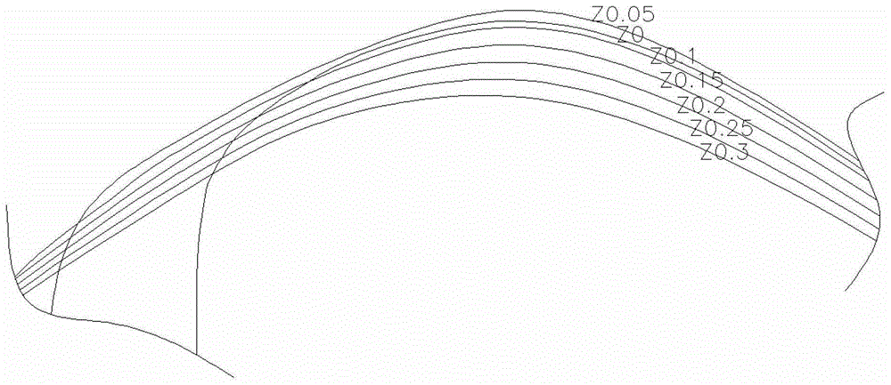
[0030] see Figure 1-Figure 7 , a transducer cabin at the bottom of a ship. At least two kinds of transducers can be placed in the transducer cabin 1. The transducer cabin 1 is a flat block-shaped shell structure with a smooth side surface, and a pair of mutually perpendicular The placement position of the long, strip-shaped transducer, the length direction of the transducer cabin 1 through the center is set as the X direction, the width direction is set as the Y direction, and the transducer cabin 1 is set close to the vertical direction of the bottom of the ship. is the Z direction; the transducer cabin 1 is divided into a left half and a right half, and the respective front and rear sides of the left and right half are symmetrical to each other; the planes of the transducer cabin 1 perpendicular to the Z axis are defined as water planes , each plane perpendicular to the X ...


PUM


Abstract

The invention relates to a ship bottom energy converter cabin. The ship bottom energy converter cabin is characterized in that an energy converter cabin (1) is of a flat block shaped shell structure which is smooth at a side peripheral surface; the length direction of the energy converter cabin (1) over the center is set as an X direction, and the width direction of the energy converter cabin (1) over the center is set as a Y direction; the vertical upward direction of the energy converter cabin (1) tightly close to the ship bottom is set as a Z direction; the energy converter cabin (1) is divided into a left half part and a right half part; the front and rear sides of the left and right half parts are symmetric to each other; the planes of the energy converter cabin (1) vertical to a Z axis are defined as a water plane, the planes of the energy converter cabin (1) vertical to an X axis are defined as a transverse section, and the planes of the energy converter cabin (1) vertical to a Y axis are defined as a longitudinal section; the water plane of the left half part of the energy converter cabin (1) is gradually enlarged along the Z direction; the water plane of the right half part of the energy converter cabin (1) is firstly enlarged gradually and then reduced gradually along the Z direction; the longitudinal section of the energy converter cabin (1) is gradually reduced along the Y direction; the transverse section of the left half part of the energy converter cabin (1) is gradually enlarged along the X axis; and the horizontal section of the right half part of the energy converter cabin (1) is gradually reduced along the X axis.

Description

technical field [0001] The invention relates to a transducer cabin at the bottom of a ship, which belongs to the technical field of the ship industry. Background technique [0002] Due to functional requirements, high-tech survey and scientific research ships have to carry special transducers, such as multi-beam, single-beam, Doppler acoustic current meters and other acoustic equipment. If these acoustic equipment are placed outside the hull of the ship bottom to receive And the range of the release signal will be wider, so advanced survey and scientific research ships will have a transducer cabin outside the hull plate at the bottom of the ship to place these devices. [0003] However, if the transducer cabin is arranged outside the bottom shell plate, it will increase the resistance of the ship, increase energy consumption, reduce the operating efficiency of the ship, and have a certain impact on the speed of the ship. The existing transducer cabin does not have a good St...

Claims


Application Information

Patent Timeline
Patent Type & Authority Patents(China)
IPC IPC(8): B63B11/00
Inventor 梁艳楠桂满海施礼军周崇冠
Owner SHANGHAI MERCHANT SHIP DESIGN & RES INST
Why Eureka
Try Eureka