Spoilers and liftless vehicles

A technology for equipment and automobiles, applied in the direction of body, body stability, vehicle components, etc., can solve the problems of increasing downforce, unsatisfactory effect, waste of energy, etc., and achieve the effect of eliminating lift, increasing ground adhesion, and uniform force on four wheels

Active Publication Date: 2017-02-22
朱晓义
View PDF10 Cites 0 Cited by
  • Summary
  • Abstract
  • Description
  • Claims
  • Application Information

AI Technical Summary

Problems solved by technology

[0002] When the car is running fast, because the bottom and side fluid paths of the car are smaller, the surface of the upper shell passes through the path to generate lift, which brings unsafe factors to the car.
Nowadays, in order to reduce the lift force when the car is running, the car uses weight to overcome the lift force. It is believed that the heavier the weight, the more stable the car, but in fact it cannot really overcome the lift force, which also causes a lot of energy waste.
In addition, cars now widely use tail fins to increase the downforce of the rear of the car, but the effect is not ideal

Method used


Image

  • Spoilers and liftless vehicles
  • Spoilers and liftless vehicles
  • Spoilers and liftless vehicles

Examples


Embodiment 1

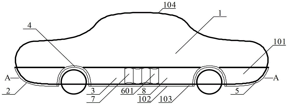
[0044] Such as figure 1 - As shown in Figure 4 (A): at the corners 103 between the front part 2, the left and right side parts 3, and the lower part and the bottom 102 of the rear part 5 of the car shell, angled spoilers are respectively arranged corresponding to their shapes 8. The angle spoiler 8 is right-angled, and its two surfaces are spoiler surfaces 606 and 607, which are provided with a spoiler surface formed by a plurality of arcs 7 extending the passage of the fluid; or a wave-shaped spoiler surface 601; Or a spoiler surface composed of a plurality of triangles 701 ; or a spoiler surface jointly formed by the arc 7 and triangles 701 (see FIG. 2(B)); wherein, the inner and outer surfaces of the spoiler surface 607 are both spoiler surfaces.

[0045] At the front and rear wheel baffles 4 corresponding to the positions around the four-wheel upper part of the automobile, an included angle spoiler 8 is established, and its spoiler surfaces 606 and 607 are formed by a plur...

Embodiment 2

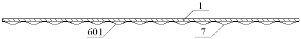
[0065] Such as figure 1 As shown in -8, at the position of the corners 103 on the left and right sides 3 between the bottom 101 of the housing 1 and the front and rear wheels of the bottom 102, corresponding to its shape, an included angle spoiler 8 is provided, and its two inner surfaces form The angle (and arc shape) is set according to the shape of the angle or radian at the corners of the lower part of the car body and the bottom, and the spoiler surfaces 606, 607 of the included angle spoiler 8 in contact with the fluid are concave or protruding shells Body surface, or arc-shaped spoiler surface 7 or wave-shaped spoiler surface 601 alternated with concavo-convex.

[0066] At the inward position of the bottom of the spoiler surface 607, an arc-shaped spoiler surface 608 of a certain height is bent downward, (see Figure 4(B)). The spoiler surfaces 608 on the left and right sides of the bottom form a middle arc-shaped fluid channel 6. The path of the fluid passing through i...


PUM


Abstract

The invention discloses a turbulent flow device and a lift-free automobile. The turbulent flow device comprises two turbulent flow faces for prolonging a fluid flowing path. The two turbulent flow faces are combined to form an included angle turbulent flow plate which is arranged at the corner between the lower part and the bottom of the automobile to prolong the fluid flowing path, so that the path is larger than the path through which upper fluid of the automobile flows. Due to continuity of the fluid, the whole fluid generates a downward pressure uniformly from the upper part of the automobile, and meanwhile, the pressure acts on a shell on the lower part and the bottom part of the automobile, so that four wheels of the automobile generate road holding forces uniformly. No lift is generated when the automobile steers quickly and slowly, so that the automobile steers more safely. Meanwhile, the invention is not only suitable for production of automobiles, but also suitable for improvement of current automobiles.

Description

technical field [0001] The invention relates to the field of automobiles and safety devices thereof, in particular to a spoiler for reducing the lift of the car and a car equipped with the spoiler. Background technique [0002] When the car is running fast, because the bottom and side fluid paths of the car are smaller, the surface of the upper shell passes through the path to generate lift, which brings unsafe factors to the car. Nowadays, in order to reduce the lift force in driving, automobiles use weight to overcome the lift force. It is believed that the heavier the weight, the more stable the car, but in fact it cannot really overcome the lift force, which also causes a large amount of energy waste. In addition, the rear wing is widely used in automobiles to increase the downforce of the rear of the automobile, but the effect is not ideal. [0003] The applicant proposed in the patent number: 201010111795.5, titled: "Inflatable Car", that a concave-convex wave shape i...

Claims


Application Information

Patent Timeline
Patent Type & Authority Patents(China)
IPC IPC(8): B62D37/02
Inventor 朱晓义
Owner 朱晓义
Why Eureka
Try Eureka