
Automatic pipe inserting device

A technology of automatic threading and driving device, used in metal processing, metal processing equipment, manufacturing tools, etc., can solve the problems of slow threading speed and high labor intensity, and achieve short assembly time, reduce labor intensity of workers, and facilitate assembly. Effect

Active Publication Date: 2013-05-01
OMS MASCH CO LTD
View PDF6 Cites 9 Cited by
  • Summary
  • Abstract
  • Description
  • Claims
  • Application Information

AI Technical Summary

Problems solved by technology

The existing assembly method is to open a plurality of holes on the fins, stack up the fins to form a fin group, and then manually insert the U-shaped tubes into the fin group one by one, which is labor-intensive and slow in tube penetration.

Method used


Image

  • Automatic pipe inserting device
  • Automatic pipe inserting device
  • Automatic pipe inserting device

Examples


Embodiment Construction

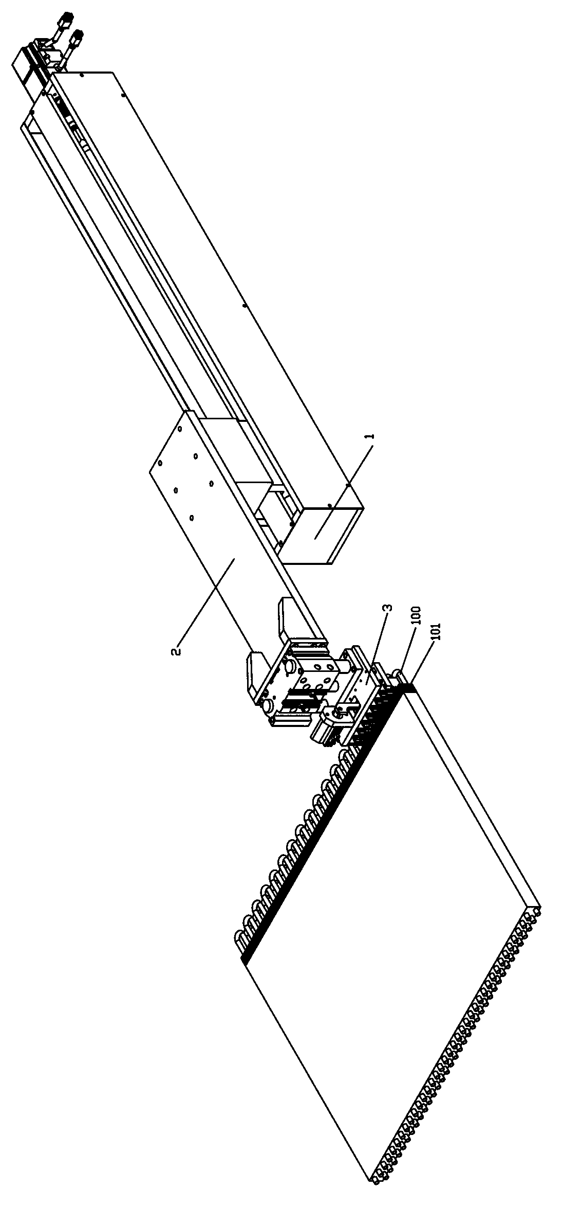
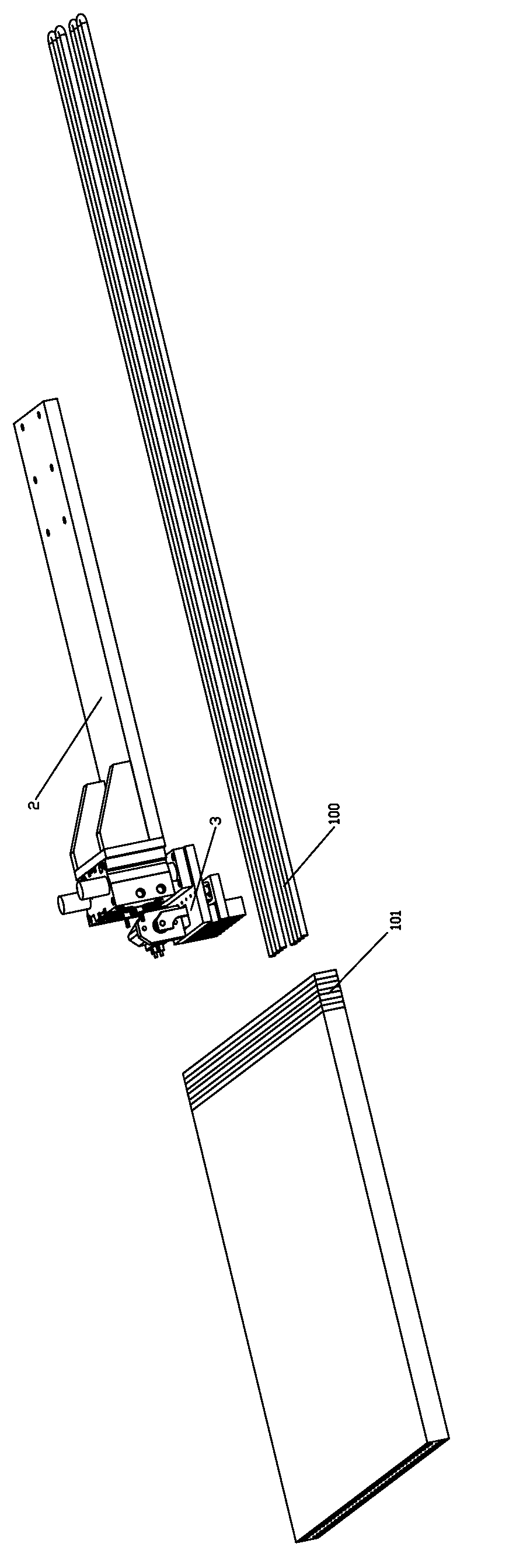
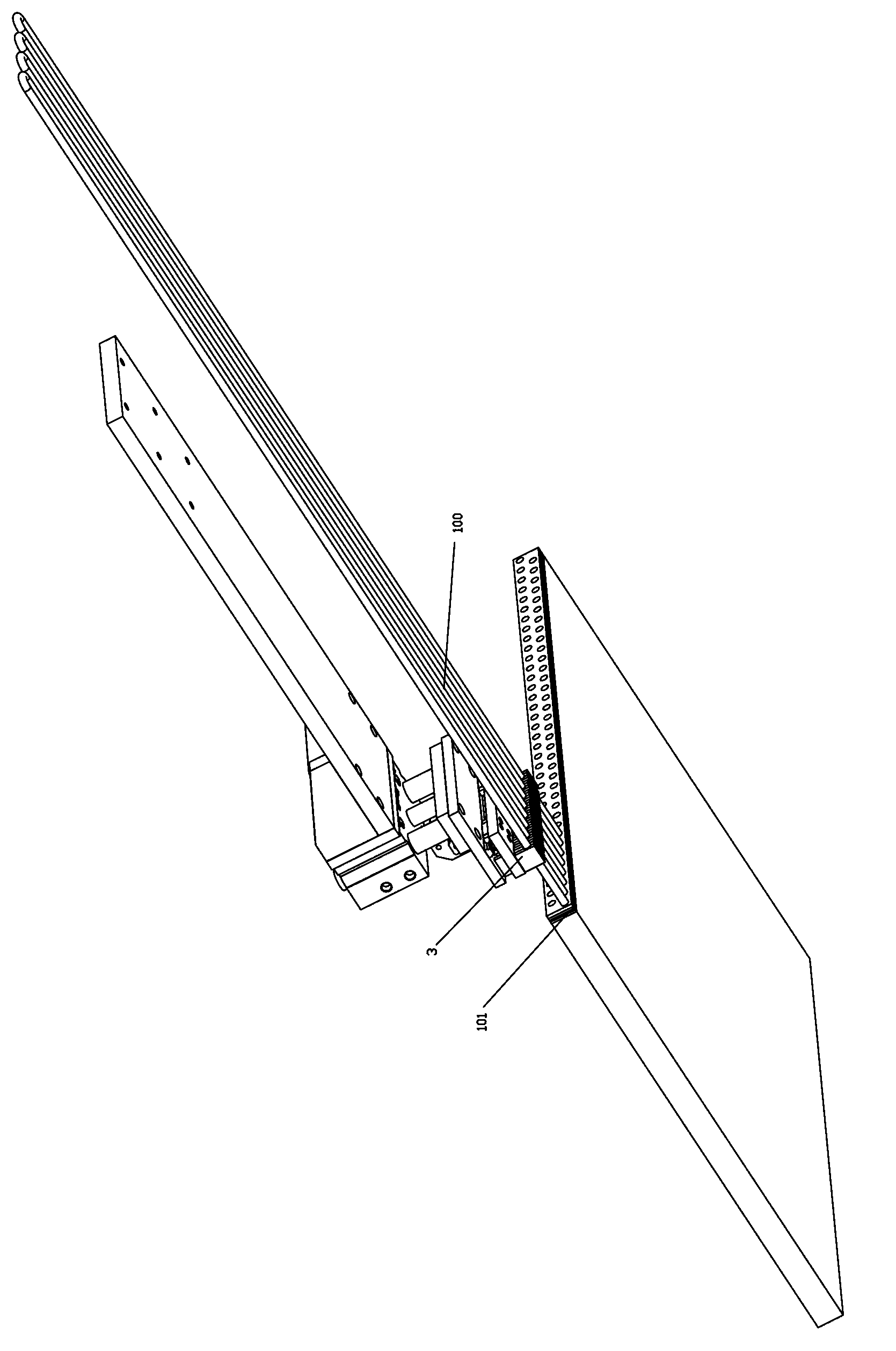
[0019] Such as figure 1 As shown, an automatic pipe threading device for inserting copper pipes into the fins in the condenser, which includes a fixed base 1, on which a feeding mechanism 2 that can move on the fixed base 1 is provided, and the feeding mechanism 2 is provided with a clamping mechanism 3 for clamping the U-shaped copper pipe 100. The clamping mechanism 3 includes a fixed base plate 31 connected to the feeder mechanism 2. The lower end of the fixed base plate 31 is provided with a plurality of fixed clips 32. The clip 32 is provided with a first semicircular groove 321 for fixing the U-shaped copper pipe 100, and the fixed substrate 31 is also provided with a driving device 33, the driving device 33 can be a cylinder, a motor, etc., and the output end of the driving device 33 Connected with a connecting piece 34 that can move on the fixed base plate 31, the connecting piece 34 is provided with a plurality of movable clips 35 that are interlaced with the fixed c...


PUM


Abstract

The invention discloses an automatic pipe inserting device for inserting copper pipes into fins in a condenser. The automatic pipe inserting device comprises a fixing base, wherein a feeding mechanism capable of moving on the fixing base is arranged on the fixing base, a clamp mechanism for clamping the U-shaped copper pipes is arranged at the front end of the feeding mechanism, the clamp mechanism comprises a fixing base plate connected with the feeding mechanism, a fixed clamp sheet is arranged at the lower end of the fixing base plate, first semi-circular grooves for fixing the U-shaped copper pipes are arranged on the fixed clamp sheet, a driving device is also arranged on the fixing base plate, the output end of the driving device is connected with a connecting component capable of moving on the fixing base plate, a movable clamp sheet arranged with the fixed clamp sheet in a staggered way is arranged on the connecting component, and second semi-circular grooves for fixing the U-shaped copper pipes are arranged on the movable clamp sheet. The automatic pipe inserting device has the advantages that multiple U-shaped copper pipes can be clamped by the clamp mechanism in a time and simultaneously inserted into metal fins, the assembly of the U-shaped copper pipes is facilitated and spends less time, and the labor intensity of workers is lowered.

Description

【Technical field】 [0001] The invention relates to an automatic pipe threading device, more particularly to an automatic pipe threading device for inserting copper pipes into fins in a condenser. 【Background technique】 [0002] A typical condenser is a combination of fins and U-shaped tubes. The fins have holes formed therethrough, and U-shaped copper tubes are formed by bending a length of tubing, usually copper, aluminum, steel, or titanium, 180 degrees around a small diameter mandrel. The existing assembly method is to have a plurality of holes on the fins, and the fins are piled up to form a fin group, and then the U-shaped tubes are manually inserted into the fin group one by one, which is labor-intensive and slow in tube penetration. 【Content of invention】 [0003] The purpose of the present invention is to overcome the deficiencies of the prior art, to provide an automatic pipe threading device for inserting copper pipes into the metal fins of the condenser, which i...

Claims


Application Information

Patent Timeline
Patent Type & Authority Applications(China)
IPC IPC(8): B23P19/00
Inventor 龙晓明肖世文王定戒
Owner OMS MASCH CO LTD
Learn More