Vibration loudspeaker
A technology of vibrating loudspeaker and basin frame is applied in the field of vibrating loudspeakers, which can solve the problems of increasing the size of vibrating loudspeakers, unable to meet the miniaturization development of portable electronic terminals, etc., so as to improve work performance, save and utilize internal space, and achieve small vibration displacement. Effect
- Summary
- Abstract
- Description
- Claims
- Application Information
AI Technical Summary
Problems solved by technology
Method used
Image

Examples
Embodiment 1
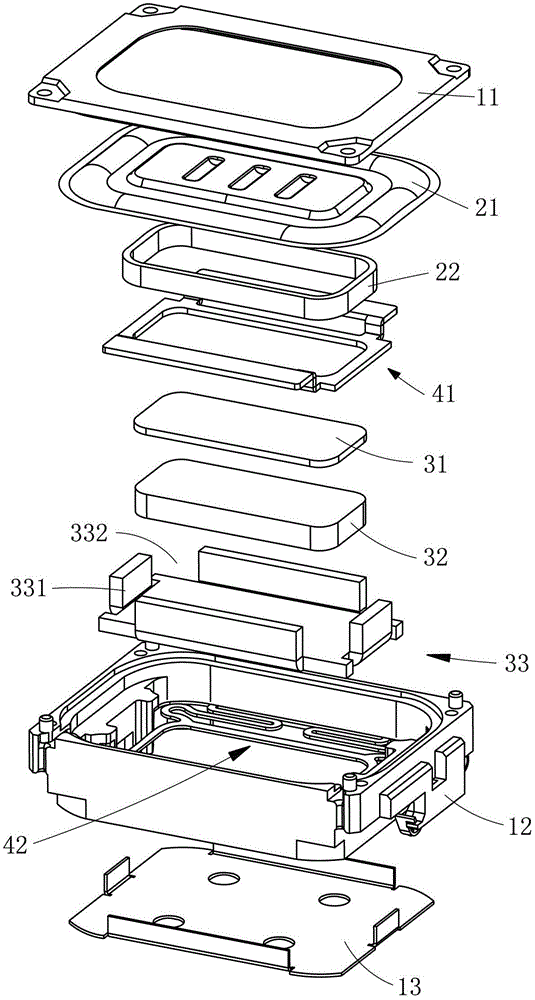
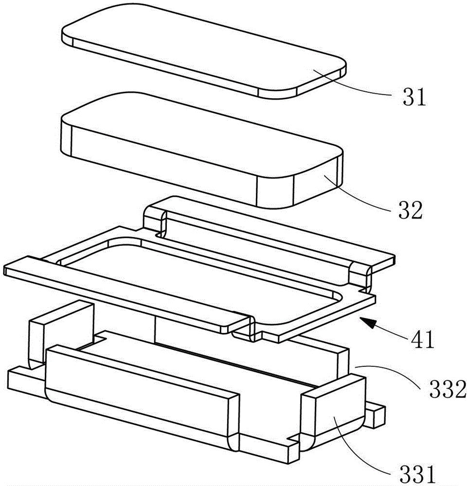
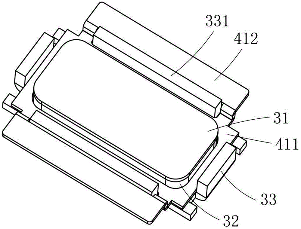
[0037] Such as figure 1 , figure 2 , image 3 , Figure 4 , Figure 5 , Image 6 with Figure 7 As shown together, a vibration speaker has a square structure and includes a housing 12, a front cover 11 and a rear cover 13 combined with the housing 12, and an inner cavity enclosed by the housing 12, the front cover 11 and the rear cover 13 contains a vibration system And the magnetic circuit system, the inner side wall of the housing 12 is provided with a shrapnel 42. The vibration system includes a diaphragm 21. The diaphragm 21 is combined with a voice coil 22. One end of the voice coil 22 is located in the magnetic gap formed by the magnetic circuit system. The system includes a basin frame 33. A magnet 32 and a washer 31 are sequentially arranged in the basin frame 33. A magnetic gap is formed between the magnet 32 and the washer 31 and the side wall 331 of the basin frame. The basin frame 33 has a square structure. The four corners of 331 are provided with notches 332; ...
Embodiment 2
[0043] Such as Figure 8 , Picture 9 , Picture 10 with Picture 11 As shown in common, the main difference between this embodiment and the first embodiment is:
[0044] The basin frame 33 has a racetrack-shaped structure, and two straight sides of the basin frame 33 are respectively provided with basin frame side walls 331.
[0045] The edge portion 422 of the shrapnel 42 is a square ring structure, the middle portion 421 of the shrapnel 42 is a racetrack-shaped ring structure corresponding to the shape of the basin frame 33, and the two straight-side edge portions 422 and the middle portion 421 are respectively provided There are two elastic arms 423; the bottom 411 of the counterweight 41 is a racetrack-shaped ring structure opposite to the shape of the basin frame 33, and the two opposite counterweights 41 are respectively provided with ear parts 412, and the ear parts 412 and The elastic arm 423 is located on the same side.
Embodiment 3
[0047] Such as Picture 12 , Figure 13 , Picture 14 with Figure 15 As shown in common, the main difference between this embodiment and the above embodiment is:
[0048] The vibrating speaker has a circular structure, and the basin frame 33, the shrapnel 42 and the counterweight 41 are all circular structures.
[0049] Three notches 332 are provided on the side wall 331 of the basin frame; three elastic arms 423 are provided between the edge portion 422 of the elastic sheet 42 and the middle portion 421 correspondingly; the counterweight 41 is provided with three side portions 413 and three side portions 413 They correspond to the positions of the three notches 332 respectively.
[0050] In this embodiment, the elastic sheet 42 is provided with three elastic arms 423, which correspond to the three notches 332 provided on the side wall 331 of the basin frame. This is only a preferred solution of the present invention. Two notches, two elastic arms are provided on the shrapnel; or ...
PUM
 Abstract
Description
Claims
Application Information
 - R&D
- Intellectual Property
- Life Sciences
- Materials
- Tech Scout
- Unparalleled Data Quality
- Higher Quality Content
- 60% Fewer Hallucinations
Browse by: Latest US Patents, China's latest patents, Technical Efficacy Thesaurus, Application Domain, Technology Topic, Popular Technical Reports.
© 2025 PatSnap. All rights reserved.Legal|Privacy policy|Modern Slavery Act Transparency Statement|Sitemap|About US| Contact US: help@patsnap.com