
Switching circuit of phase shift and limited bipolar control manner and control method thereof

A technology for switching circuits and control methods, applied in output power conversion devices, electrical components, climate sustainability, etc., can solve problems such as circulating current phenomenon, narrow range, power device damage, etc., to achieve capacity saving, simple and practical circuits Effect

Inactive Publication Date: 2013-04-24
SOUTH CHINA UNIV OF TECH
View PDF3 Cites 8 Cited by
  • Summary
  • Abstract
  • Description
  • Claims
  • Application Information

AI Technical Summary

Problems solved by technology

The full-bridge inverter usually adopts the phase-shift control method and the limited bipolar control method. The full-bridge inverter realizes soft switching in a wide range and high efficiency under the limited bipolar control method, but the light load and no-load loss are very serious. , there is some damage to the power device; and in the phase-shift control mode, the range of soft switching is narrow, there is a circulation phenomenon, and the IGBT heating phenomenon is aggravated, but compared with the limited bipolar control mode, the full-bridge inverter is shifting Under light load and no load in phase control mode, the loss is small

Method used


Image

  • Switching circuit of phase shift and limited bipolar control manner and control method thereof
  • Switching circuit of phase shift and limited bipolar control manner and control method thereof
  • Switching circuit of phase shift and limited bipolar control manner and control method thereof

Examples


Embodiment Construction

[0023] The present invention will be described in further detail below in conjunction with the accompanying drawings.

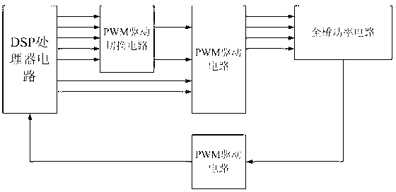
[0024] Such as figure 1 As shown, a switching circuit of phase shifting and limited bipolar control mode, including a DSP processor circuit, an output voltage and a current feedback circuit, a PWM driving switching circuit, a PWM driving circuit and a full bridge power circuit; the DSP processor The circuits are respectively connected to the output voltage and current feedback circuit, the PWM drive switching circuit, and the PWM drive circuit; the full bridge power circuit is respectively connected to the output voltage and current feedback circuit and the PWM drive circuit; the PWM drive switch circuit is also connected to the PWM drive Circuit connection; the DSP processor circuit is used to generate 6-way PWM signals, and according to the output voltage and output current to determine whether to use a phase-shift control method or a limited bipolar contro...


PUM


Abstract

The invention discloses a switching circuit of a phase shift and limited bipolar control manner and a control method of the switching circuit of the phase shift and limited bipolar control manner. The switching circuit comprises a digital signal processor (DSP) circuit, an output voltage and current feedback circuit, a pulse-width modulation (PWM) driving switching circuit, a PWM driving circuit and a full-bridge power circuit. The DSP circuit is respectively connected with the output voltage and current feedback circuit, the PWM driving switching circuit and the PWM driving circuit. The full-bridge power circuit is respectively connected with the output voltage and current feedback circuit and the PWM driving circuit. The PWM driving switching circuit is further connected with the PWM driving circuit. The control method comprises that whether a phase shift control manner or a limited bipolar control manner is used is judged by the DSP circuit according to output power. The switching circuit of the phase shift and limited bipolar control manner and the control method of the switching circuit of the phase shift and limited bipolar control manner solve the problems that the full-bridge power circuit has ring current, is serious in insulated gate bipolar translator (IGBT) heating, small in range of soft switching and the like under phase shift control while load is heavy, and are capable of avoiding the problem that the full-bridge power circuit is large in consumption under the limited bipolar control when load is empty and light.

Description

technical field [0001] The invention relates to the technical field of a high-frequency switching power supply, in particular to a switching circuit and a control method of a phase-shifting and limited bipolar control mode. Background technique [0002] When the voltage and current ratings of the power switch tubes are the same, the output power of the converter is usually proportional to the number of power switch tubes used. Therefore, currently in the application of medium and high-power DC power supplies, a full-bridge converter is usually used. The full-bridge converter includes Full bridge inverter and output rectification filter circuit. The full-bridge inverter usually adopts the phase-shift control method and the limited bipolar control method. The full-bridge inverter realizes soft switching in a wide range and high efficiency under the limited bipolar control method, but the light load and no-load loss are very serious. , there is some damage to the power device;...

Claims


Application Information

Patent Timeline
Patent Type & Authority Applications(China)
IPC IPC(8): H02M7/5387
CPCY02B70/1491Y02B70/10
Inventor 杜贵平
Owner SOUTH CHINA UNIV OF TECH
Learn More