Winding structure of transformer

A winding structure and transformer technology, applied in the direction of transformer/inductor coil/winding/connection, etc., can solve the problems of increased insulation distance, increased main material consumption, poor heat dissipation, etc., to achieve small insulation distance, high efficiency, and convenient wiring Effect

Inactive Publication Date: 2013-04-24
WUJIANG TRANSFORMER
View PDF8 Cites 3 Cited by
  • Summary
  • Abstract
  • Description
  • Claims
  • Application Information

AI Technical Summary

Problems solved by technology

The disadvantages of this structure are: the structure of the low-voltage winding is complicated, and the winding is difficult; the high-voltage winding can only adopt a layered structure in consideration of the convenience of wiring. For transformers with a capacity of 3150KVA and above, the heat dissipation is poor, the mechanical strength is obviously insufficient, and short-circuit resistance The capacity is also affected to a certain extent; because the high-voltage winding is adjacent to the iron core, and the high-voltage outgoing line must be drawn out in the main airway, the insulation distance between the iron core and the high voltage, and between the high voltage and the low voltage has increased, and the amount of main materials has increased. , the cost of materials is further increased

Method used


Image

  • Winding structure of transformer

Examples


Embodiment

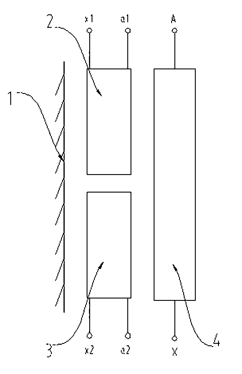
[0019] refer to figure 1 As shown, the winding structure of the transformer includes a high-voltage winding 4, a low-voltage winding located between the iron core 1 and the high-voltage winding 4, and the low-voltage winding includes an upper low-voltage winding 2 and a lower low-voltage winding 3. Wherein, the upper low-voltage winding 2 and the lower low-voltage winding 3 are arranged in parallel along the axial direction of the transformer, and the high-voltage winding 4 is wound continuously.

[0020] The upper low-voltage winding 2 and the lower low-voltage winding 3 are wound with copper foil. And the first and last heads a1 and x1 of the lead wires of the upper low-voltage winding 2 are drawn from the upper part of the winding, the first and last joints a2 and x2 of the lead wires of the lower low-voltage winding 3 are drawn from the lower part of the winding, and the first and last joints A of the lead wires of the high-voltage winding 4 , X are drawn from the up...


PUM


Abstract

The invention relates to a winding structure of a transformer, particularly to a foil low-voltage winding structure for high voltage of a rectifier transformer. The winding structure comprises a high voltage winding and at least two parallelly connected low voltage windings arranged between an iron core and the high voltage winding, wherein the low voltage windings are made of copper foil or aluminum foil through winding, and a plurality of low voltage windings are in parallel connection and arranged along the axial direction of the transformer. According to the winding structure of the transformer, the production process is simple, wire outlet is convenient, the insulation distance is small, materials are saved, and consumption is reduced.

Description

technical field [0001] The invention relates to a low-voltage winding structure of a transformer, in particular to a foil-type low-voltage winding structure for a high voltage rectifier transformer. Background technique [0002] Rectifier transformers for low-voltage and high-current transmission are mainly used in power transmission for DC motors, such as armatures and excitations of rolling mills. In the prior art, the low-voltage winding of the rectifier transformer adopts double-cake continuous winding, and every two cakes is one circuit, and multiple circuits are connected in parallel. The high voltage adopts layer winding, and the outgoing line is drawn from the main empty channel. The order of the entire transformer body from the inside to the outside is iron core - high voltage winding - low voltage winding. The disadvantages of this structure are: the structure of the low-voltage winding is complicated, and the winding is difficult; the high-voltage winding can on...

Claims


Application Information

Patent Timeline
Patent Type & Authority Applications(China)
IPC IPC(8): H01F27/28H01F27/29
Inventor 关银环郭凯涛朱庆民
Owner WUJIANG TRANSFORMER
Why Eureka
Try Eureka