Concentrated power supply rack-mounted equipment function module hot plug control system

A technology for device functions and control systems, applied in the field of communications, can solve the problem of high cost of hot-swap control circuits, and achieve the effects of significant cost-effectiveness, simple circuit implementation, and reduced system costs.

Active Publication Date: 2013-04-24
MAIPU COMM TECH CO LTD
View PDF5 Cites 11 Cited by
  • Summary
  • Abstract
  • Description
  • Claims
  • Application Information

AI Technical Summary

Problems solved by technology

[0003] The technical problem to be solved by the present invention is to provide a centralized power supply rack-type equipment function module hot-swap control system for the disadvantage of high cost of the hot-swappable control circuit of the functional module, which can ensure good and reliable effect of slow power-on of the control function module cost reduction

Method used


Image

  • Concentrated power supply rack-mounted equipment function module hot plug control system
  • Concentrated power supply rack-mounted equipment function module hot plug control system
  • Concentrated power supply rack-mounted equipment function module hot plug control system

Examples


Embodiment

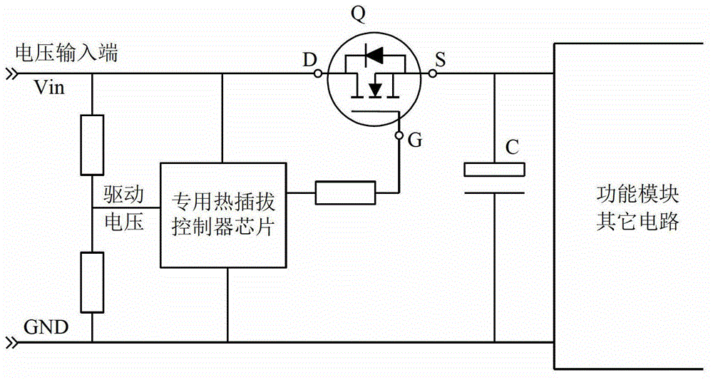
[0033] In this example, the function module hot swap control circuit structure is as follows Figure 4 As shown, the switching device adopts an N-channel CMOS field effect transistor Q, and the control circuit is composed of a first resistor R1, a second resistor R2, and a capacitor C1. One end of the first resistor R1 is connected to the driving voltage, the other end is connected to the second resistor R2, the other end of the second resistor R2 is grounded, the capacitor C1 is connected in parallel with the second resistor R2, and the connection point of the first resistor R1 and the second resistor R2 (ie, the capacitor C1 The non-grounded terminal of the switch device is connected to the gate of the field effect transistor Q as the control terminal of the switching device, and the drain and source of the field effect transistor Q are connected in series with the voltage input terminal. In this example, the resistors R1 and R2 can be ordinary metal film resistors, and the ca...


PUM


Abstract

The invention relates to a rack-mounted equipment function module hot plug control system, and discloses a concentrated power supply rack-mounted equipment function module hot plug control system which aims at the defect that a function module hot plug control circuit in the prior art is high in cost. The concentrated power supply rack-mounted equipment function module hot plug control system can reduce the cost on the premise of ensuring good and reliable slow power-on effects of a control function module. The concentrated power supply rack-mounted equipment function module hot plug control system comprises a control circuit and a switching element. The control circuit is connected with drive voltage, the switching element is connected with a voltage input end in series, and a control end of the switching element is connected with the control circuit. The voltage input end is connected with a main power supply of equipment. The control circuit comprises a first resistor, a second resistor and a capacitor. The first resistor is connected with the second resistor in series, the first resistor is connected with the drive voltage, and the second resistor is connected to the ground. The capacitor is connected with the second resistor in parallel, and a non-grounding end of the capacitor is connected with the control end of the switching element. The concentrated power supply rack-mounted equipment function module hot plug control system is mainly applied to communication equipment.

Description

Technical field [0001] The present invention relates to communication technology, in particular to a hot-swappable control system for function modules of centralized power supply rack-mounted equipment in the communication field. Background technique [0002] In modern communication equipment, rack-mounted / non-isolated low-voltage backplane power supply equipment is becoming more and more common. The functional modules of this type of equipment are usually powered by the equipment. The biggest advantage is that the power supply part can save isolated DC / DC (direct current- DC) converter cost, functional modules can be flexibly configured according to user needs. At the same time, for the convenience of use, these functional modules can be hot-swapped on the rack (power-swappable functional modules). One of the technical problems that need to be solved when the functional module supports hot-plugging is that it cannot cause strong interference to the power system of the device du...

Claims


Application Information

Patent Timeline
Patent Type & Authority Applications(China)
IPC IPC(8): G05B19/418
Inventor 程鸿博
Owner MAIPU COMM TECH CO LTD
Why Eureka
Try Eureka