Receptacle sub

A socket and sleeve technology, applied in the field of plugs, darts, and drop weights, can solve problems such as restriction and inability to maintain flow rate, and achieve the effect of reducing drilling time

Inactive Publication Date: 2013-04-24
VETCO GRAY
View PDF5 Cites 4 Cited by
  • Summary
  • Abstract
  • Description
  • Claims
  • Application Information

AI Technical Summary

Problems solved by technology

However, since the burst disk must fit within the dart, it is necessarily smaller than the diameter of the fluid column above it
Thus, while the burst disk does provide a faster drain than the aforementioned fluid ports, it still restricts flow and cannot maintain a flow rate large enough to drain as fast as a pullable string

Method used


Image

  • Receptacle sub
  • Receptacle sub
  • Receptacle sub

Examples


Embodiment Construction

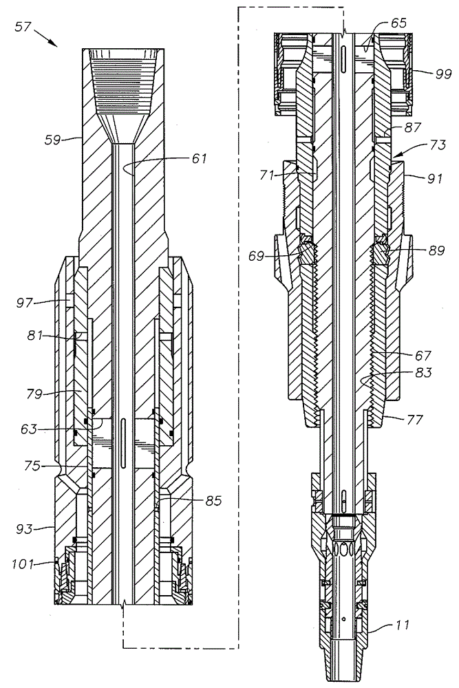
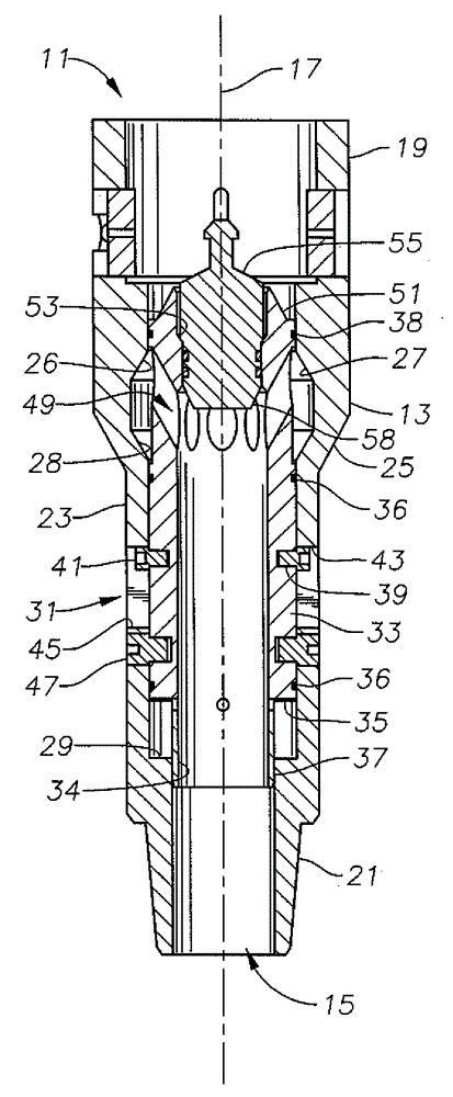
[0021] The invention will now be described more fully hereinafter with reference to the accompanying drawings, which show embodiments of the invention. This invention may, however, be embodied in many different forms and should not be construed as limited to the illustrated embodiments set forth herein. Rather, these embodiments are provided so that this disclosure will be thorough and complete, and will fully convey the scope of the invention to those skilled in the art. Like numbers refer to like elements throughout, and primary labels, if used, refer to similar elements in alternative embodiments.

[0022] In the following discussion, numerous specific details are set forth in order to provide a thorough understanding of the present invention. It will be apparent, however, to one skilled in the art that the present invention may be practiced without such specific details. Additionally, details pertaining to drilling rig operation, casing hanger placement and placement, et...


PUM


Abstract

The invention relates to a receptacle sub, and discloses the receptacle sub (11) which improves discharging flow rate during a period a running tool (57) is got back. A tool or sub 11 includes a sleeve 33 with a bypass port 49 in a central bore 15 defined by a tubular body 13. The sleeve is selectively moveable from an upper position to a lower position. A seal 38 on the sleeve seals the sleeve to the bore while a retainer 47 holds the sleeve in the upper position. A bypass passage 27 in the body is in fluid communication with the bypass port. A drop member 55 lands on the sleeve, blocking downward flow through the sleeve so that pressure builds up until retainer or shear pin 47 shears, thus enabling fluid to flow from above the bore through the bypass passage and via the port. Other inventions relate to a running tool with a hydraulically actuated function and a bypass passage with a cross sectional flow area that is at least equal to a flow area through a central passage.

Description

technical field [0001] The present invention relates generally to drop hammers, plugs or darts used to operate the function of running well tools, and in particular to darts with dart landing shoulders to variably allow fluid to flow in Bypass sleeve for flow through falling parts after tool operation. Background technique [0002] Darts, drop hammers or plugs are often used to actuate hydraulics within the wellhead or wellbore during drilling and completion. Typically, a running tool is run to a predetermined location in the wellhead. The drop weight then falls into the running string supporting the running tool and is pumped down to seat at a shoulder within or axially below the running tool. The fluid pressure behind the drop hammer then increases until the fluid pressure reaches a level sufficient to actuate the hydraulic functions of the running tool. The running tool can then be retrieved from the wellbore. This can be done during wet retrieval. During wet retriev...

Claims


Application Information

Patent Timeline
Patent Type & Authority Applications(China)
IPC IPC(8): E21B41/00
CPCE21B34/103E21B2034/007E21B34/14E21B23/04E21B23/08E21B21/103E21B2200/06E21B34/142
Inventor N.P.格特
Owner VETCO GRAY
Why Eureka
Try Eureka