Liquid increasing device for washing wells

A liquid device and well-washing technology, which is applied in the direction of cleaning equipment, wellbore/well parts, earthwork drilling and production, etc., can solve the problems of large damage, leakage of well-washing fluid, and oil layer pollution, so as to avoid well killing and increase output Fluid volume, effect of reducing pump leakage

Inactive Publication Date: 2013-04-24
SHAANXI ZHONGMING ENERGY INVESTMENT
View PDF0 Cites 0 Cited by
  • Summary
  • Abstract
  • Description
  • Claims
  • Application Information

AI Technical Summary

Problems solved by technology

The traditional casing hot washing and wax removal method is the main wax removal method used in the oilfield of this block, but this wax removal method has the following disadvantages: (1) The hot washing time is long, and the average hot washing time of oil wells with a well depth of 2000M is generally as long as 5h; (2) Low cleaning efficiency and low heat utilization rate
Most of the heat is lost in the casing wall and the area near the borehole wall during casing thermal cleaning, and part of the heat is lost into the formation with the leaked flushing fluid, and less than 30% of the heat is actually used for thermal flushing and wax removal; (3) The leakage of well flushing fluid is serious, the average single well flushing fluid leakage is about 10 cubic meters, which has caused serious pollution to the oil layer; (4) For the wells with glass fiber reinforced plastic sucker rods, the wells are flushed at a high temperature during hot cleaning liquid damages the
In response to the above problems, we have taken the following measures: (1) Implement chemical wax removal and anti-wax in conjunction with hot washing. Since the application of this method, although the hot washing cycle has been extended to a certain extent, there is still the problem that the washing fluid pollutes the oil layer
(2) An anti-pollution packer is used as a supporting tool. Although this tool can prevent the well-washing fluid from entering the formation to a certain extent, due to the influence of high-temperature well-washing fluid on the rubber sleeve of the packer, it is easy to age and crack. Field application has caused many downhole accidents and is not commonly used now
However, due to reasons such as sand in the formation, overhaul accidents are often caused, and it is no longer used.
(4) For wells with glass fiber reinforced plastic sucker rods, the temperature of the well cleaning fluid should not be too high during hot washing, but this will lead to incomplete waxing hot washing of oil wells

Method used


Image

  • Liquid increasing device for washing wells

Examples


Embodiment 1

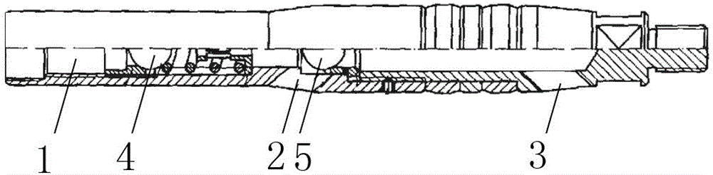
[0012] A liquid booster for well flushing according to the present invention comprises a body, the upper part of the body is provided with an upper liquid inlet hole 1, and the lower part of the upper liquid inlet hole 1 is provided with a liquid outlet hole 2, and the upper liquid inlet hole 1 and the liquid outlet hole 2 are connected to each other. Connected, the liquid inlet hole is provided with a liquid inlet ball valve 4, the liquid inlet ball valve 4 is arranged on the body through a spring, the liquid outlet hole 2 is provided with a ball valve chamber, and the inside of the ball valve chamber is provided with a movable ball valve 5, the ball valve The minimum cross-sectional diameter of the chamber is larger than the diameter of the ball valve.

[0013] The liquid booster for well flushing according to the present invention is installed at the lower part of the oil well pump. When flushing the well, first remove the plug of the oil pump, and the heated well flush flui...

Embodiment 2

[0015] This embodiment is basically the same as Embodiment 1, except that a lower liquid inlet hole 3 is provided at the lower part of the liquid outlet hole 2 in this embodiment, and the lower liquid inlet hole 3 and the liquid outlet hole 2 communicate with each other.

[0016] During normal oil pumping, the downstroke stage: the well fluid enters the device from the lower liquid inlet hole 3, the movable ball valve 5 moves upward under the impact of the well fluid, and the well fluid flows to the liquid outlet hole 2, and then enters the hollow sucker rod and the oil pipe. The annulus completes a liquid feeding process; the upstroke stage: the liquid feeding ball valve 4 is downward, which can effectively seal the upper liquid of the liquid booster of the well flusher. At the same time, with the completion of the upstroke, the well fluid sucked during the downstroke is pumped to the ground to complete a drainage process. During the entire swabbing process, the device divide...


PUM


Abstract

The invention relates to a liquid increasing device for washing wells and belongs to equipment for washing wells. The liquid increasing device for washing wells includes a body and is characterized in that an upper liquid inlet hole is arranged on the upper portion of the body, a liquid outlet hole is arranged on the lower portion of the upper liquid inlet hole, the upper liquid inlet hole is communicated with the liquid outlet hole, a liquid inlet ball valve is movably arranged on the liquid inlet hole, and a ball valve chamber with a movable ball valve inside is arranged on the liquid outlet hole. The liquid increasing device for washing wells can avoid well killing function to oil layers caused by well washing liquid during traditional thermal washing and pollution to oil layers after well washing liquid is immersed in the oil layers, improves swabbing capacity of a oil well pump, reduces pump leakage and improves pump efficiency.

Description

technical field [0001] The invention relates to a device for washing wells. Background technique [0002] At present, some old oilfields that have been developed for a long time have deep liquid level, low water content, high wax content and high freezing point. The traditional casing hot washing and wax removal method is the main wax removal method used in the oilfield of this block, but this wax removal method has the following disadvantages: (1) The hot washing time is long, and the average hot washing time of oil wells with a well depth of 2000M is generally as long as 5h; (2) The well washing efficiency is low and the heat utilization rate is low. Most of the heat is lost in the casing wall and the area near the borehole wall during casing thermal cleaning, and part of the heat is lost into the formation with the leaked flushing fluid, and less than 30% of the heat is actually used for thermal flushing and wax removal; (3) The leakage of well flushing fluid is serious...

Claims


Application Information

Patent Timeline
Patent Type & Authority Applications(China)
IPC IPC(8): E21B37/00
Inventor 王梅玫
Owner SHAANXI ZHONGMING ENERGY INVESTMENT
Why Eureka
Try Eureka