Eureka AIR delivers breakthrough ideas for toughest innovation challenges, trusted by R&D personnel around the world.

Charge type vacuum oil filter

A vacuum oil purifier, electric charge technology, applied in the direction of filtration separation, filtration loop, separation method, etc., can solve the problems of low filtration precision, low degree of automation and purification efficiency, slow water evaporation, etc., to improve work efficiency and improve dehydration. and degassing efficiency, the effect of improving filtration accuracy

Inactive Publication Date: 2013-04-24
昆山威胜达环保设备有限公司
View PDF4 Cites 4 Cited by
  • Summary
  • Abstract
  • Description
  • Claims
  • Application Information

AI Technical Summary

Problems solved by technology

[0003] At present, all vacuum oil purifiers in China have the following disadvantages: (1) There is no air humidity sensor, manual sampling is required to detect whether the water has been removed, and the degree of automation and purification efficiency is low; (2) The heater is used to directly heat the oil The product evaporates the water in it, and the surface temperature of the heating tube can reach several hundred degrees. Under high temperature, the aging and deterioration of the oil product will be accelerated, which is harmful to the oil product; (3) it can only effectively remove the water in the oil product, and it will not affect the oil product. The impurity removal effect is not obvious, and it is impossible to filter out particles smaller than 1 μm. The reactor is composed of multiple Laschig circles. Although the oil mist sprayed onto the reactor can form an oil film, and the moisture and gas in the oil can be volatilized, but because the reactor needs to absorb the heat of the oil, the temperature of the oil is lowered. Therefore, the evaporation of water in the oil is relatively slow and inefficient

Method used


Image

  • Charge type vacuum oil filter

Examples


Embodiment Construction

[0018] The present invention will be further described below in conjunction with the accompanying drawings.

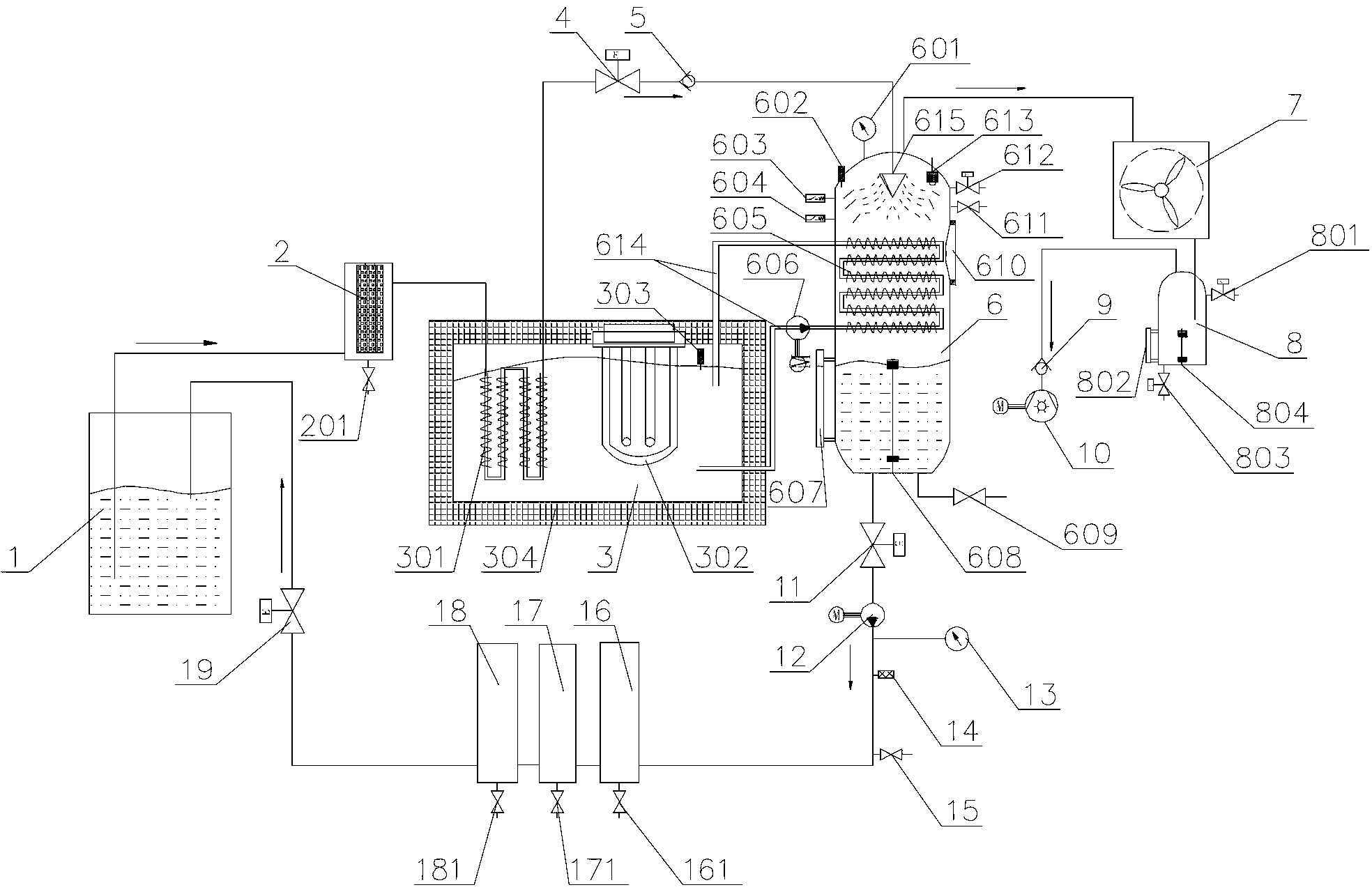
[0019] like figure 1 Shown is a charge-type vacuum oil filter, including an oil circuit and a heat transfer oil circuit.

[0020] The oil circuit includes an oil tank 1 containing oil, a coarse filter 2, a heat exchanger A301, an atomizer 615, a vacuum chamber 6, a pre-filter 16, a charging mixer 17, a collector 18 and oil pipelines , the oil outlet of the oil tank 1 is connected to the oil inlet of the coarse filter 2 through the oil pipeline, and the oil outlet of the coarse filter 2 is connected to the oil inlet of the heat exchanger A301 through the oil pipeline The oil outlet of the heat exchanger A301 communicates with the oil inlet of the atomizer 615 through the oil pipeline, and the atomizer 615 is arranged on the top of the vacuum chamber 6, and the vacuum chamber 6 The oil outlet communicates with the pre-filter 16 , the charging mixer 17 and the collector...


PUM


Abstract

The invention discloses a charge type vacuum oil filter which comprises an oil loop and a heat conduction oil loop, wherein the oil loop comprises an oil tank for containing oil, a heat exchanger A, an atomizer, a vacuum chamber and an oil pipeline; the heat conduction oil loop comprises a heating tank for containing heat conduction oil, a heat exchanger B and a heat conduction oil pipeline; a heating tube is arranged inside the heating tank; the heat exchanger A is positioned inside the heating tank; and the heat exchanger B is positioned inside the vacuum chamber and below the atomizer. The charge type vacuum oil filter provided by the invention adopts a heat conduction oil indirect low-temperature heating technique, and the oil is heated by using the heat exchanger A, so that damage caused by the fact that the oil is directly heated at high temperature is avoided; the heat exchanger B is used as a reactor to further heat the oil, and the oil mist sprayed on the reactor is formed into an oil film, so that the working efficiency is greatly improved; due to an additionally arranged charging flow mixer and a collector, the filtering precision is improved; and due to an additionally arranged air humidity sensor, the moisture of the oil can be detected on line.

Description

technical field [0001] The invention relates to an oil filter, in particular to a charge-type vacuum oil filter. Background technique [0002] Turbine oil, hydraulic oil, anti-fuel oil and other oils contain impurities, water and gas pollution, especially the steam turbine oil in operation will inevitably contact with water, water and oil react to form acid, colloid and sludge, which can also The additives in the oil are precipitated, and the water will reduce the lubricating performance of the oil, corrode the metal, and accelerate the wear of the hydraulic components. The water will also cause the sticking of the control valve, which is extremely harmful to the equipment. Mechanical impurities and sludge will damage the oil film, accelerate the wear of equipment, block valve cores and filters, and cause equipment failure during operation. Therefore, water and mechanical impurities in the oil must be removed to keep the oil in a very clean state, which can Reduce the failu...

Claims


Application Information

Patent Timeline
IPC IPC(8): B01D36/00
Inventor 刘威高小玉
Owner 昆山威胜达环保设备有限公司
Why Eureka
Eureka Blog
Learn More