Silicone negative pressure drainage apparatus

A technology of negative pressure drainage and silica gel, applied in wound drainage devices, suction devices, etc., can solve problems such as diastolic difficulties, troublesome production, lengthy drainage process, etc., and achieve the effects of shortening drainage time, convenient production, and quick operation

Inactive Publication Date: 2013-04-24
CONOD MEDICAL
View PDF4 Cites 1 Cited by
  • Summary
  • Abstract
  • Description
  • Claims
  • Application Information

AI Technical Summary

Problems solved by technology

[0002]Negative pressure drainage device is mainly used for the drainage of thoracic cavity and abdominal cavity patients after puncture operation, which has been reported in patent literature, such as the multifunctional chest drainage device recommended by CN2782100Y Abdominal puncture negative pressure drainage device is composed of three-way tube, drainage tube and negative pressure drainage container (the patent is called negative pressure drainage device). The following technical problems are exposed: when the air in the negative pressure drainage container is driven out and is in a deflated state, that is, there is often a risk of diastolic difficulty after being in a negative pressure state
The common shortcomings of these two patents are: it is more laborious to expel the air in the negative pressure drainage container; the production is very troublesome, because the spring needs to be set in the cavity of the negative pressure drainage container during the manufacturing process
In addition, because the drainage method is single-point or single-channel drainage, the drainage process is lengthy, which is not conducive to shortening the treatment time for patients with puncture

Method used


Image

  • Silicone negative pressure drainage apparatus

Examples


Embodiment Construction

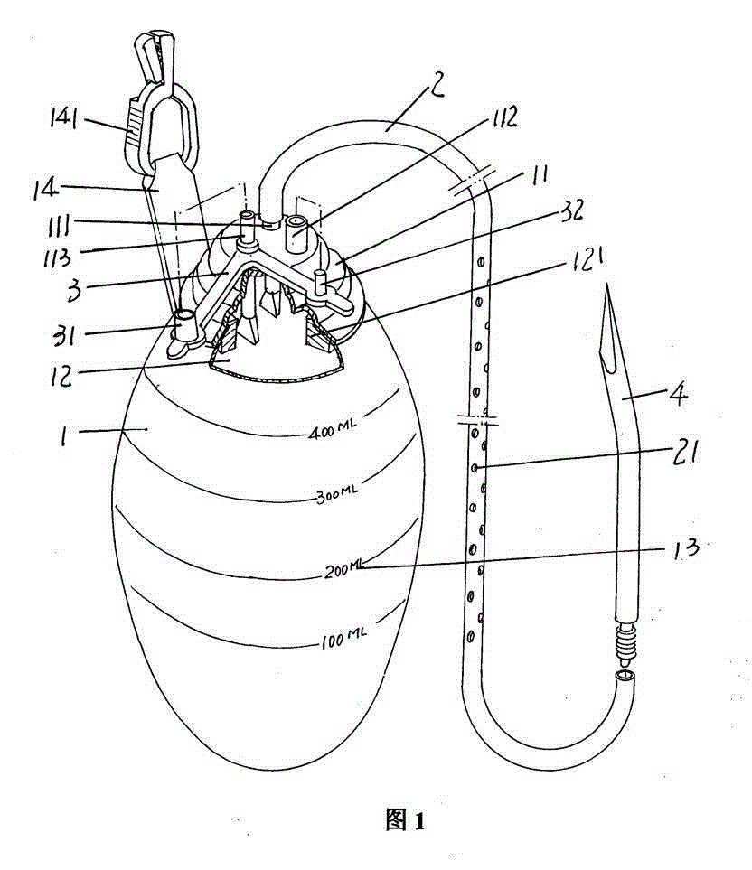
[0012] please see figure 1 , a silicone airbag 1 shaped like a goose egg and made of silicone rubber is provided. An airbag sealing cover 11 is fixed on the top of the silicone airbag 1 by means of a pressure ring 121 arranged in the cavity 12. The airbag sealing cover 11 is formed with a drainage tube interface 111 , a liquid drainage interface 112 and an exhaust port 113 communicating with the cavity 12 . In this embodiment, a plug cover 3 is sleeved on the exhaust port 113. As shown in the figure, the shape of the entire plug cover 3 is V-shaped, and there is a first plug on the plug cover 3. Cover 31 and a second plug cap 32 , the first plug cap 31 is matched with the exhaust port 113 , and the second plug cap 32 is matched with the liquid discharge port 112 . It should be noted that the aforementioned plug cover sheet 3 can also be transferred to the liquid discharge interface 112 .

[0013] One end of a drainage tube 2 is matched with the aforementioned drainage t...


PUM


Abstract

The invention discloses a silicone negative pressure drainage apparatus, and belongs to the technical field of medical appliance. The silicone negative pressure drainage apparatus comprises a silicone air bag and a drainage pipe. An air bag seal cover is arranged on the top of the silicone air bag in a combination mode, a drainage pipe port, a liquid exhaust port and a gas exhaust port are arranged on the silicone air bag, wherein the drainage pipe port, the liquid exhaust port and the gas exhaust port are communicated with the air bag cavity of the silicone air bag. A plug cover piece is sleeved on the liquid exhaust port or the gas exhaust port, a first plug cover and a second plug cover are arranged on the plug cover piece, the first plug cover is matched with the gas exhaust port, the second plug cover is matched with the liquid exhaust port, one end of the drainage pipe is connected with the drainage port in a matching mode, and the other end of the drainage pipe is provided with liquid collecting holes which are communicated the pipe cavity of the drainage pipe in a dense state. The silicone negative pressure drainage apparatus has the advantages of being labor-saving and fast to operate, convenient and cheap to manufacture due to the fact that the silicone negative pressure drainage apparatus is in no need of using a spring as an existing technology, capable of achieving multi-channel drainage, and shortening drainage time of a patient.

Description

technical field [0001] The invention belongs to the technical field of medical equipment, and in particular relates to a silicone negative pressure drainage device. Background technique [0002] The negative pressure drainage device is mainly used for the drainage of thoracic cavity and abdominal cavity patients after puncture surgery. It has been reported in the patent literature. A typical example is the multifunctional thoracoabdominal puncture negative pressure drainage device recommended by CN2782100Y, which consists of a three-way tube, a drainage tube and The negative pressure drainage container (the patent is called negative pressure drainage device), because the negative pressure drainage container of this patent is a simple wrinkled body structure, so the following technical problems will be exposed during use: When the air in the negative pressure drainage container After the expulsion is in a deflated state, that is, in a negative pressure state, there is often t...

Claims


Application Information

Patent Timeline
Patent Type & Authority Applications(China)
IPC IPC(8): A61M1/00A61M27/00
Inventor 沈建东
Owner CONOD MEDICAL
Why Eureka
Try Eureka