Capillary inlet flow regulator

A technology of inlet flow and regulator, which is applied in the direction of flow control without auxiliary power, function valve type, application, etc., can solve the problems of narrow working pressure range, low assembly efficiency, high processing precision requirements, etc., and achieve the increase of working pressure range , The starting pressure difference is reduced, and the effect of pressure compensation is realized

Active Publication Date: 2014-05-28
CHINA AGRI UNIV
View PDF5 Cites 0 Cited by
  • Summary
  • Abstract
  • Description
  • Claims
  • Application Information

AI Technical Summary

Problems solved by technology

[0006] Generally speaking, the flow passage structure of the flow regulator is one of the main factors affecting its performance. The existing capillary inlet flow regulator flow passage structure in the market has defects, the flow regulation performance is not ideal, and the starting pressure difference is shown. Disadvantages such as too large, insufficient flow stability, and narrow suitable working pressure range; cylindrical silicone tubes or other complex elastic regulators require high processing accuracy, and manufacturing deviations are not easy to control, resulting in unstable performance of the flow regulator , low assembly efficiency

Method used


Image

  • Capillary inlet flow regulator
  • Capillary inlet flow regulator
  • Capillary inlet flow regulator

Examples


Embodiment 1

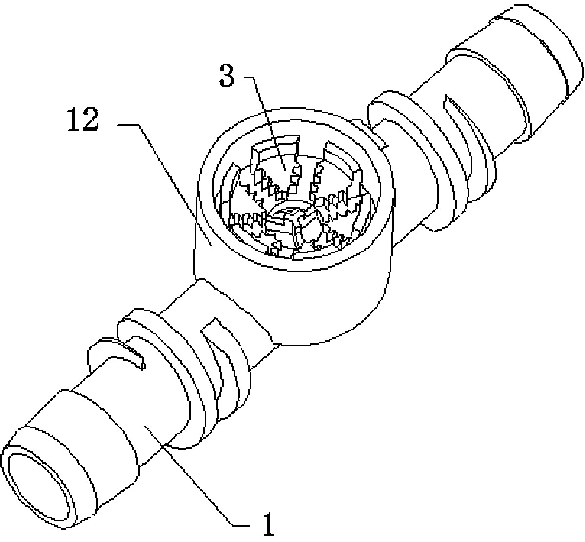
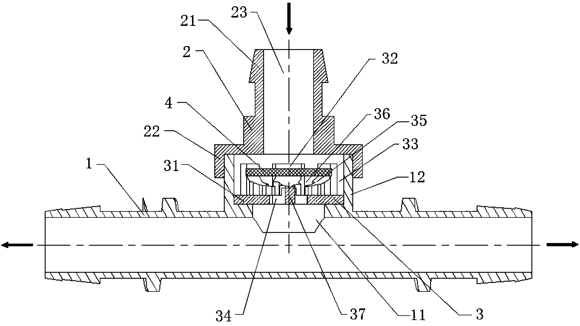
[0030] like figure 1 , figure 2 As shown, Embodiment 1 includes a water outlet base 1 , a water inlet cover 2 , a core seat 3 and a disc-shaped elastic diaphragm 4 .

[0031] like figure 1 , figure 2 As shown, the water outlet base 1 is a cylindrical pipe, the side wall of the water outlet base 1 is provided with a circular hole 11, and the outer wall of the water outlet base 1 in the circumferential direction of the circular hole 11 is integrally provided with a cylindrical interface pipe 12, and the cylindrical interface pipe The inner diameter of 12 is greater than the diameter of the circular hole 11, and the top of the cylindrical interface pipe 12 is connected to the water inlet cover 2 by threads, or inserted into the water inlet cover 2. The circular hole 11 and the water inlet cover 2 are used as the water inlet, and the two ends of the water outlet base 1 are used as the water outlet.

[0032] like figure 2 As shown, the water inlet cover 2 includes an inte...

Embodiment 2

[0036] like Image 6 As shown, the second embodiment includes a water outlet base 1 , a water inlet cover 2 , a core seat 3 and a disc-shaped elastic diaphragm 4 .

[0037] like Image 6 As shown, the water outlet base 1 is a cylindrical pipe, one end of the water outlet base 1 is used as the water inlet, and the other end is used as the water outlet. The water inlet end is equal to the circular hole 11 provided on the side wall of the water outlet base 1 in Embodiment 1, and the outer wall of the water outlet base 1 in the circumferential direction of the water inlet end is integrally provided with a cylindrical interface pipe 12, and the inner diameter of the cylindrical interface pipe 12 is larger than The diameter of the water inlet end, the top of the cylindrical interface pipe 12 is connected to the water inlet cover 2 by threads, or inserted in the water inlet cover 2 .

[0038] The structures of the water inlet cover 2, the core seat 3 and the disc-shaped elastic dia...


PUM


Abstract

The invention relates to a capillary inlet flow regulator. The capillary inlet flow regulator is characterized by comprising a cylindrical water outlet base, a water inlet cover, a core seat and a disk-shaped elastic membrane, wherein a round hole is arranged on the sidewall of the water outlet base, a cylindrical joint pipeline is arranged on the circumference of the round hole, the water inlet cover is arranged on the top portion of the cylindrical joint pipeline, a water inlet communicated with the cylindrical joint pipeline is arranged on the cover plate, the core seat is arranged in the cylindrical joint pipeline and comprises a round bottom plate, a cylindrical retaining wall is arranged on the top portion of the round bottom plate, a water inlet ring is formed between the periphery of the cylindrical retaining wall and the cylindrical joint pipeline, a central water outlet is arranged at the center of the round bottom plate, a plurality of fan rings protruding upwards are arranged at intervals on the circumference of the central water outlet, surfaces of the fan rings are arc-shaped, groove runners are formed between every two adjacent fan rings, a central jacking column protruding upwards is arranged in the central water outlet, detachable adjusting plates are respectively arranged at positions, corresponding to the groove runners, on the cylindrical retaining wall, and the disk-shaped elastic membrane is arranged in the cylindrical retaining wall and above the fan rings and the central jacking column.

Description

technical field [0001] The invention relates to a flow regulator in agricultural water-saving irrigation equipment, in particular to a capillary inlet flow regulator suitable for micro-irrigation systems and having a series of flow values. Background technique [0002] In the drip irrigation system, due to the friction loss and the change of terrain, the pressure of each point of the branch pipe in the irrigation area is different, which makes the working pressure of each capillary inlet different, resulting in the different water output of each capillary, which reduces the uniformity of irrigation. The pressure compensation dripper can reduce the flow difference caused by the pressure deviation of the pipe network and improve the irrigation uniformity of the micro-irrigation system, but such a system is expensive. Proceeding from the actual situation in our country, installing a capillary flow regulator can improve the irrigation uniformity of the system and is very economi...

Claims


Application Information

Patent Timeline
Patent Type & Authority Patents(China)
IPC IPC(8): G05D7/01F16K17/24A01G25/16
Inventor 李光永张琛
Owner CHINA AGRI UNIV
Why Eureka
Try Eureka