
Wall thickness linear model-based pipe mechanical property hydro-bugling testing method

A technology of hydraulic bulging and testing methods, which is applied in the direction of applying stable tension/pressure to test the strength of materials, etc., which can solve the problems of discontinuous experiments and difficult measurement of pipe wall thickness, so as to improve the testing efficiency and achieve reliable material performance results. Experimental Ease of Effect

Inactive Publication Date: 2013-04-17
HARBIN INST OF TECH
View PDF2 Cites 22 Cited by
  • Summary
  • Abstract
  • Description
  • Claims
  • Application Information

AI Technical Summary

Problems solved by technology

[0003] The present invention solves the problems of difficult measurement of pipe wall thickness and discontinuous experiments in the existing hydraulic bulging test method for mechanical properties of pipes, and further provides a hydraulic bulging test method for mechanical properties of pipes based on a linear model of wall thickness

Method used


Image

  • Wall thickness linear model-based pipe mechanical property hydro-bugling testing method
  • Wall thickness linear model-based pipe mechanical property hydro-bugling testing method
  • Wall thickness linear model-based pipe mechanical property hydro-bugling testing method

Examples


specific Embodiment approach 1

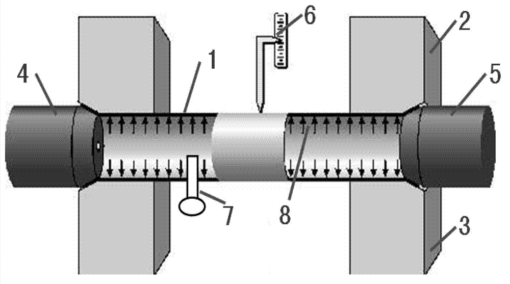
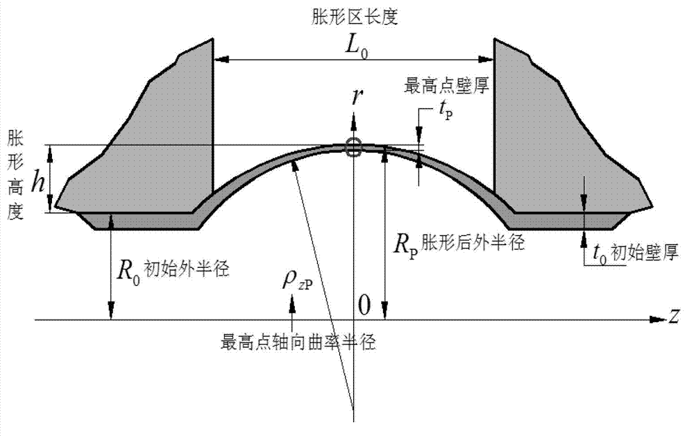
[0026] Specific implementation mode one: as Figure 1~2 As shown, the steps of the hydraulic bulging test method for the mechanical properties of pipes based on the wall thickness linear model in this embodiment are as follows:

[0027] Step 1. Measure the initial wall thickness t of the pipe to be tested 1 0 , the outer radius R of the pipe to be tested 1 0 and the length of the bulging zone L 0 ;

[0028] Step 2, placing the pipe material 1 to be tested between the upper mold 2 and the lower mold 3, and sealing the two ends of the pipe material 1 to be tested by the left sealing punch 4 and the right sealing punch 5;

[0029] Step 3: Fill the high-pressure liquid medium 8 into the pipe material 1 to be tested, and the pressure of the high-pressure liquid medium 8 is 15-300 MPa;

[0030] Step 4: Real-time record the pressure of the high-pressure liquid medium 8 and the bulging height h during the bulging process of the pipe 1 to be tested until the pipe 1 to be tested rup...

specific Embodiment approach 2

[0046] Specific implementation mode two: as figure 1 As shown, in step 3, the pressure of filling the high-pressure liquid medium 8 into the pipe 1 to be tested is 30-200 MPa. Others are the same as in the first embodiment.

specific Embodiment approach 3

[0047] Specific implementation mode three: as figure 1 As shown, in steps 1 and 5, an ultrasonic thickness gauge is used to measure the wall thickness of the pipe 1 to be tested. The range of the ultrasonic thickness gauge is 0-20 mm, and the measurement accuracy is 0.01 mm. Others are the same as in the first or second embodiment.


PUM

PropertyMeasurementUnit
lengthaaaaaaaaaa

Abstract

The invention discloses a wall thickness linear model-based pipe mechanical property hydro-bugling testing method, to solve the problems that the conventional pipe mechanical property hydro-bugling testing method is difficult to measure pipe wall thickness and discontinuous in experiment. The method comprises the following steps of: firstly, testing the initial wall thickness, the outer radius and the bulging area length of the pipe to be tested; secondly, putting the pipe to be tested between an upper die and a lower die, and sealing two ends of the pipe to be tested; thirdly, filling a high-pressure liquid medium into the pipe to be tested; fourthly, recording the pressure and the bulging height of the high-pressure liquid medium in the bulging process of the pipe to be tested in real time till the pipe to be tested is cracked; fifthly, measuring the wall thickness of a crack point of the pipe to be tested, and calculating and obtaining the wall thickness of each moment in the bulging process according to the wall thickness linear model; and sixthly, calculating and obtaining an equivalent stress stain curve of the pipe. The method is applied to pipe mechanical property hydro-bugling testing.

Description

technical field [0001] The invention relates to a hydraulic bulging testing method for mechanical properties of pipes. Background technique [0002] Accurate testing of the mechanical properties of materials is an important basis for reasonably characterizing the mechanical properties of materials and realizing the determination of process parameters and numerical simulation analysis in the process of material forming. Uniaxial tensile test is one of the main methods to test the mechanical properties of materials. For plates, when the mechanical properties along different directions in the plane of the plate are different, samples can be taken along different directions on the plate, and the stress-strain curves of the corresponding directions of the plate can be tested by uniaxial tensile experiments. For pipes, there are also differences in mechanical properties along the axial and hoop directions. At this time, the axial mechanical properties of the pipe can still be te...

Claims


Application Information

Patent Timeline
Patent Type & Authority Applications(China)
IPC IPC(8): G01N3/12
Inventor 苑世剑林艳丽何祝斌
Owner HARBIN INST OF TECH
Learn More