Fan with novel structure

A fan, a novel technology, applied to the components of the pumping device for elastic fluid, pump control, non-variable pumps, etc., can solve the problems that the fan cannot reach the air outlet, and the direction of the air outlet cannot be adjusted arbitrarily, and achieve The effect of novel structure and increased flexibility

Active Publication Date: 2013-04-17
铜陵易难信息科技有限公司
View PDF5 Cites 5 Cited by
  • Summary
  • Abstract
  • Description
  • Claims
  • Application Information

AI Technical Summary

Problems solved by technology

[0004] The invention provides a fan with a novel structure, the main purpose of which is to overcome the problems that the air outlet of the existing fan cannot meet the comfort and softness required by people, and the air outlet direction cannot be adjusted arbitrarily.

Method used


Image

  • Fan with novel structure
  • Fan with novel structure
  • Fan with novel structure

Examples


Embodiment 1

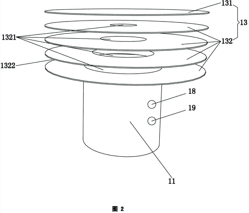
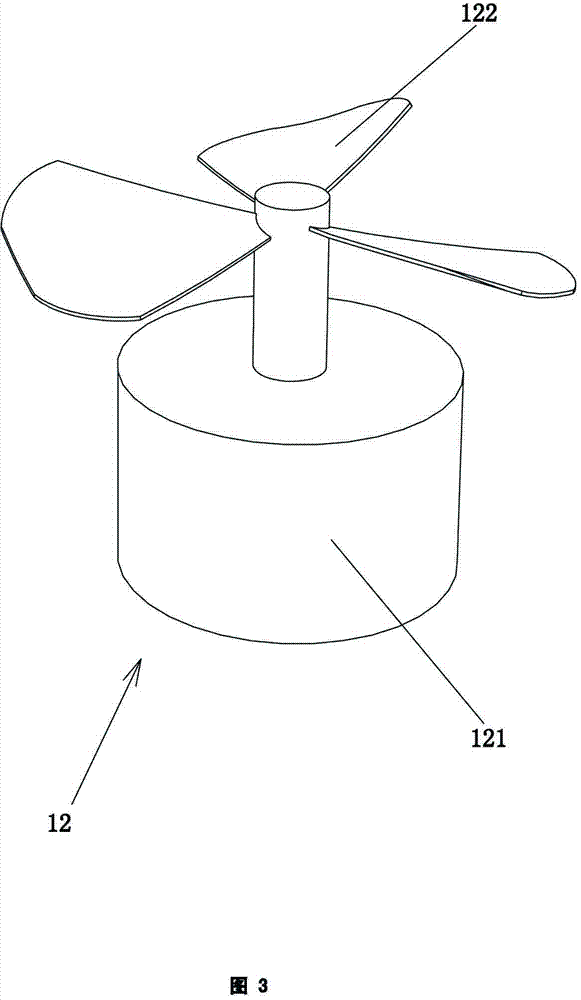
[0024] Refer to attached figure 1 , figure 2 with image 3 . A fan with a novel structure, including a fan body 1, the fan body 1 includes a hollow base 11, an air supply mechanism 12 installed in the base 11, and an air supply port on the top surface of the base 11 (not shown in the figure) The air outlet mechanism 13 and an air direction adjustment mechanism 14 are connected, and the air outlet mechanism 13 includes a top cover 131 and a plurality of wind deflectors 132 located below the top cover 131 and arranged at intervals from top to bottom. The top cover 131 and A plurality of air deflectors 132 are circular, and each air deflector 132 is provided with an air outlet through hole 1321. The apertures of the air outlet through holes 1321 on the plurality of air deflectors 132 are all different, and they are formed from bottom to top. An air outlet channel (not shown in the figure) whose hole diameter gradually narrows, and an air outlet 1322 is formed between two adja...

Embodiment 2

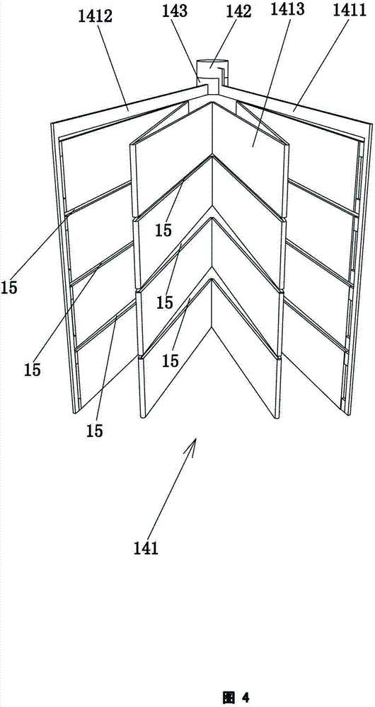
[0029] Refer to attached Image 6 with Figure 7 . The specific implementation method of this embodiment is basically the same as that of Embodiment 1, the difference is that: the air guide assembly includes a plurality of air guide units 1411 arranged at intervals in the vertical direction and surrounding each air outlet, each The wind guide unit 1411 includes a front guide plate 14111, a rear guide plate 14112, and a foldable middle guide plate 14113 connected between the front guide plate 14111 and the rear guide plate 14112, which can be expanded and folded. The motors 142, 143 of the gearbox, the two motors 142, 143 can be installed on the top surface middle part of the top cover, and the two motors 142, 143 are respectively connected with the transmission shaft 1421, 1431, and the two transmission shafts 1421, 1431 left , right arrangement, one side of the front and rear guide plates 14111, 14112 are respectively connected with the two transmission shafts 1421, 1431, a...


PUM


Abstract

The invention relates to a fan with a novel structure. The fan comprises a fan body, wherein the fan body comprises a hollow structure base, an air supply mechanism arranged in the base, an air discharge mechanism communicated with the air supply mechanism on the top face of the base, and a wind direction adjustment mechanism, wherein the air discharge mechanism comprises a top cover and a plurality of air deflectors arranged from the top to the bottom at intervals, wherein the air deflectors are positioned under the top cover, each air deflector is provided with air discharge through holes, the air discharge through holes from the bottom to the top form an air discharge channel, the hole diameter of which is gradually contracted, and an air discharge port is formed between the two adjacent air deflectors. The fan is novel in structure. The wind is softer than the wind generated by the existing fan after passing through the air discharge channel which is gradually contracted from the bottom to the top, so people feel more comfortable in the wind blowing process. The wind direction adjustment mechanism can realize continuous air supply of the fan at 0-360 degrees, so that different wind blowing requirements of people can be met. Moreover, hidden blades are safer.

Description

technical field [0001] The invention relates to a household appliance, in particular to a fan with a novel structure. Background technique [0002] Fans have been widely used in every family and various places, bringing great convenience to people's lives in summer. With the continuous improvement of daily needs and technology, the shape and types of fans are also increasing, such as desk fans, floor fans, bladeless fans, etc. [0003] Existing fans generally transfer the surrounding air to the air flow through the rotation of the fan blades, so as to achieve the effect of cooling and relieving heat. In order to meet a larger use space, the existing fans generally have the function of "shaking the head", but this function has a limited range of use, the direction of the wind can only be changed within a certain range and cannot be adjusted arbitrarily, and the wind blowing to people The source is discontinuous; in addition, the air volume of the existing fan is controlled ...

Claims


Application Information

Patent Timeline
IPC IPC(8): F04D25/08F04D27/00F04D29/40
Inventor 林秀寒林水龙
Owner 铜陵易难信息科技有限公司
Why Eureka
Try Eureka