


Quick Research
Generate reliable direction feasibility study reports for your R&D in just a few steps.

Technical Q&A
Discover and master advanced knowledge NOW. Basics, ideas, possibilities, all at once.

Find Solutions
As an expert in R&D theories, this can generate solutions to your technical problems instantly.

Evaluate Feasibility
Analyze your overall solution with one click, know your potential R&D risks in advance.

Monitor Landscape
Get weekly tech updates, stay abreast of the latest tech innovations and key insights.
Holder, holder unit, and scribe device
A scribing device and holder technology, which is used in glass cutting devices, fine working devices, glass manufacturing equipment, etc., can solve problems such as poor rotation of the scribing wheel, reduce poor rotation, and inhibit the decline or breakage of end face strength. Uneven strength, easy-to-rotate effect
- Summary
- Abstract
- Description
- Claims
- Application Information
AI Technical Summary
Problems solved by technology
Method used
Image

Examples
Embodiment approach 1
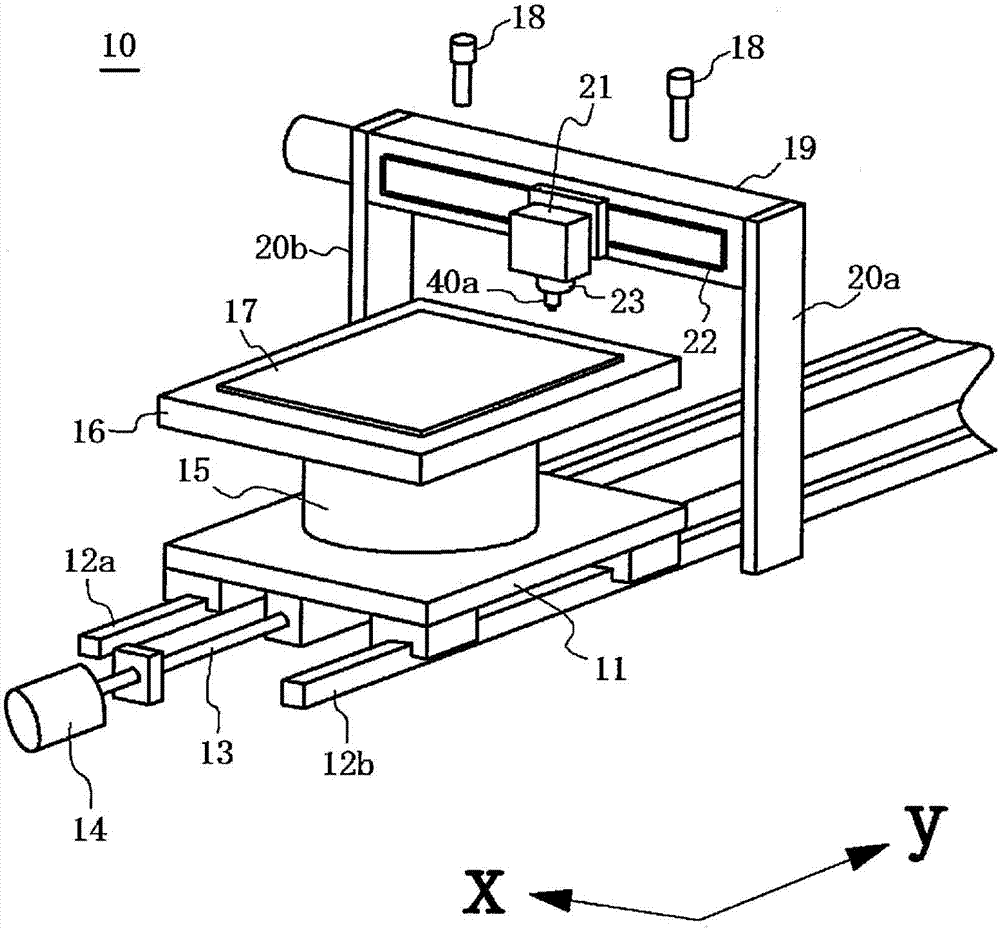
[0061] figure 1 A schematic diagram of the scribing device 10 according to Embodiment 1 of the present invention is shown in . In the scribing device 10, the moving table 11 is held movably in the y-axis direction along a pair of guide rails 12a and 12b. The mobile table 11 is screwed with the ball screw 13 . The ball screw 13 is rotated by the drive of the motor 14, and moves the moving table 11 in the y-axis direction along the guide rails 12a and 12b.
[0062] A motor 15 is provided on the upper surface of the moving table 11 . The motor 15 is a part that rotates the stage 16 on the xy plane and positions it at a specific angle. The brittle material substrate 17 is placed on the table 16 and held by a not-shown vacuum suction mechanism or the like. Two CCD (Charge Coupled Device, Charge Coupled Device) cameras 18 for imaging the alignment mark of the brittle material substrate 17 are installed on the upper part of the scribing device 10 . In addition, in the scribing d...
Embodiment 1
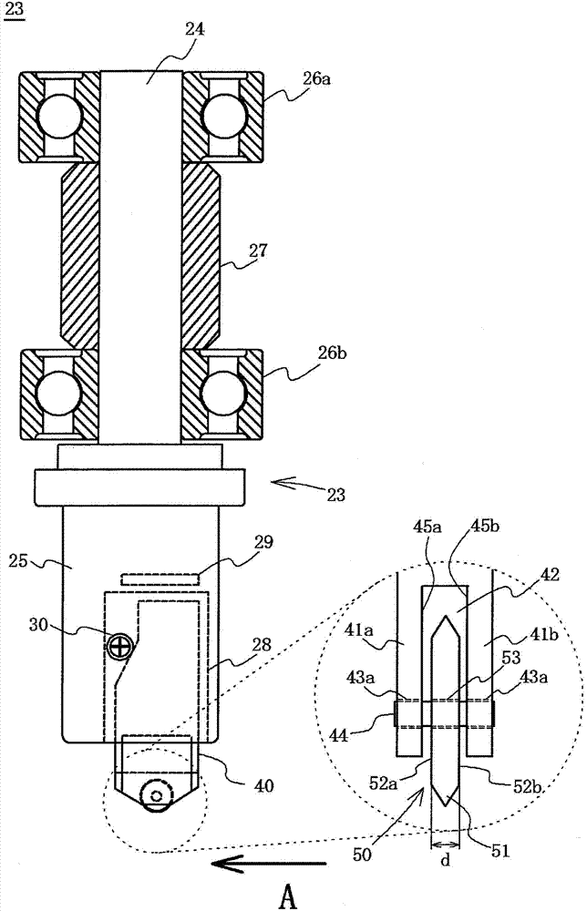
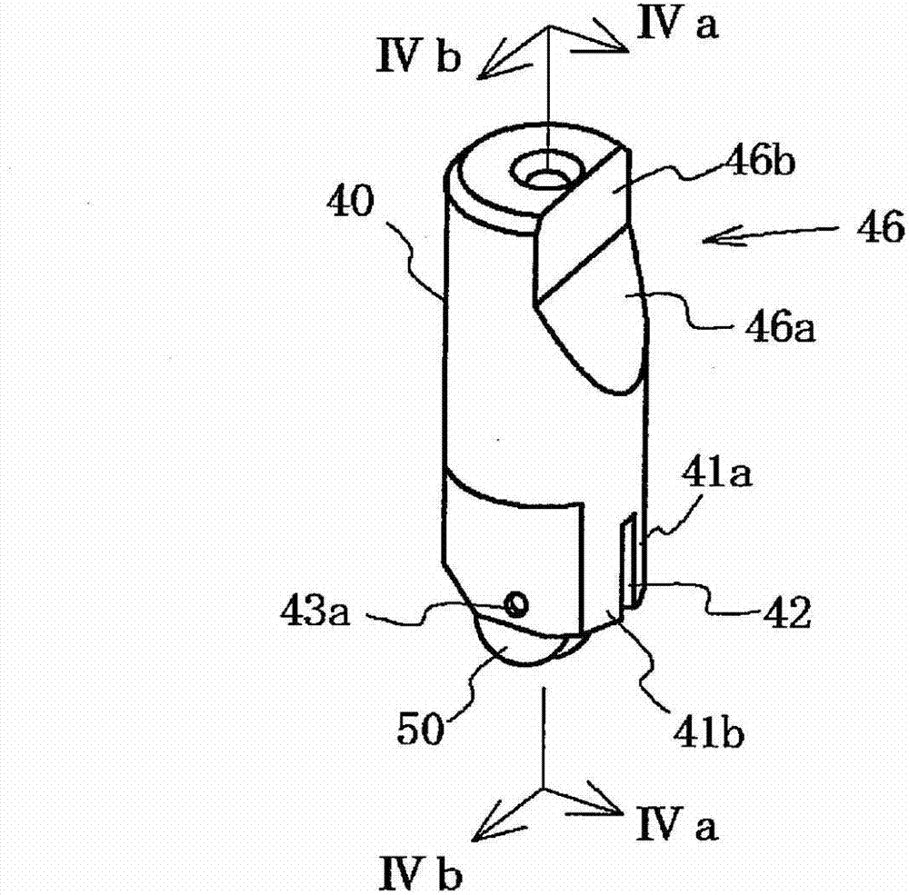
[0076] Figure 4 A cross-sectional view of the holder 40a of Example 1 is shown in . also, Figure 4 (a) is along image 3 Sectional view of line IVa-IVa, Figure 4 (b) is along image 3 Sectional view of line IVb-IVb. In addition, the scribing wheel 50 is indicated by a dotted line.
[0077] Arc-shaped grooves 46 as an example of recessed portions are respectively formed on the inner walls 45a, 45b of the holder 40a. The groove 46 is provided at a position facing the side surfaces 52 a and 52 b of the scribing wheel 50 . Therefore, even if foreign matter such as glass shavings enters between the inner walls 45a, 45b and the side surfaces 52a, 52b, the foreign matter stays in the groove 46, and the influence on the rotation of the scribing wheel 50 can be reduced. In addition, since the groove 46 is extended to a position that does not face the side surfaces 52a, 52b of the scribing wheel 50, the foreign matter trapped in the groove 46 will be discharged to the sides 52...
Embodiment 2
[0080] Figure 5 The structure of the holder 40b of Example 2 is shown in . also, Figure 5 (a) is along image 3 Sectional view of line IVa-IVa, Figure 5 (b) is along image 3 Sectional view of line IVb-IVb. In addition, the scribing wheel 50 is indicated by a dotted line.
[0081] Three grooves 47a, 47b, and 47c are formed on the inner walls 45a, 45b of the holder 40b, respectively. The grooves 47 a , 47 b , 47 c extend from positions facing the side surfaces 52 a , 52 b of the scribing wheel 50 to positions not facing them, similarly to the grooves 46 of the first embodiment. In addition, it extends toward the vertical direction G up to the end of the holding groove 42 . Therefore, even if foreign matter such as glass shavings enters between the inner walls 45a, 45b and the side surfaces 52a, 52b, the foreign matter can be discharged through the grooves 47a, 47b, 47c, thereby reducing rotation failure of the scribing wheel 50 .
[0082] In addition, the three groov...
PUM
 Abstract
Description
Claims
Application Information
 - R&D Engineer
- R&D Manager
- IP Professional
- Industry Leading Data Capabilities
- Powerful AI technology
- Patent DNA Extraction
Browse by: Latest US Patents, China's latest patents, Technical Efficacy Thesaurus, Application Domain, Technology Topic, Popular Technical Reports.
© 2024 PatSnap. All rights reserved.Legal|Privacy policy|Modern Slavery Act Transparency Statement|Sitemap|About US| Contact US: help@patsnap.com