Speed control system actuator for pipeline cleaning and detection device
A technology of detection equipment and speed control, which is applied in cleaning methods and tools, chemical instruments and methods, etc., and can solve problems such as high operation speed of pigging detection equipment and operation risks of pipeline operators
- Summary
- Abstract
- Description
- Claims
- Application Information
AI Technical Summary
Problems solved by technology
Method used
Image
Examples
Embodiment 1
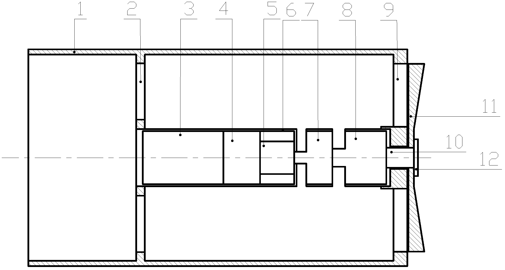
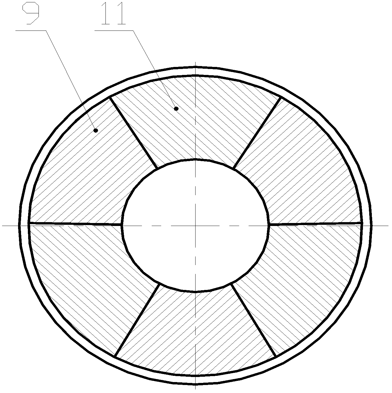
[0037] Embodiment 1. The structure of this example is as figure 1 shown. Its main components include discharge cylinder 1, rear bracket 2, battery pack 3, control module 4, motor 5, sealed chamber body 6, coupling 7, reduction box 8, fixed fan blade 9, transmission shaft 10, movable fan Leaf 11, gland 12. In the sealed compartment 6 at the center of the rear support 2 fixedly connected to the rear of the discharge cylinder 1 (with the direction of airflow entering the front), a battery pack 3, a control module 4, a motor 5, and a motor are installed in sequence from the back to the front. The shaft of 5 passes through the hole of the sealed chamber body 6 and is connected with the shaft coupling 7, the shaft coupling 7 is connected with the transmission shaft 10 through the reduction box 8, and the transmission shaft 10 stretches out from the fixed fan blade 9 at the front end of the discharge cylinder 1 and then connects with the shaft coupling 7. The movable fan blade 11 i...
Embodiment 2
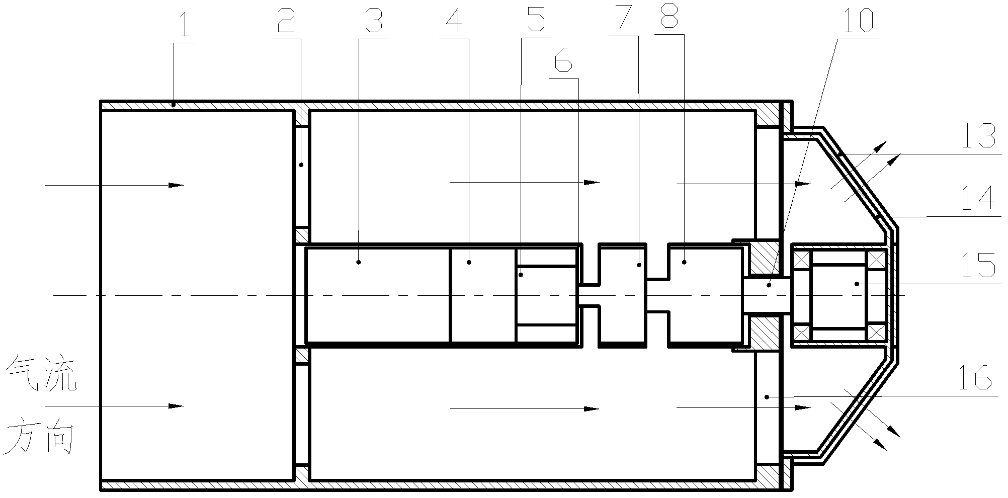
[0043] Embodiment 2. The structure of this example is as figure 2 shown. Its main components include discharge cylinder 1, rear bracket 2, battery pack 3, control module 4, motor 5, sealed chamber body 6, coupling 7, reduction box 8, fixed fan blade 9, transmission shaft 10, movable fan Leaf 11, gland 12, fixed cover 13, rotating cover 14, rotating shaft 15, front support 16. In the sealed compartment 6 at the center of the rear bracket 2 fixedly connected to the front of the discharge cylinder 1 (with the direction of airflow entering as the front), a battery pack 3, a control module 4, a motor 5, and a motor 5 are installed in sequence from front to back. The shaft passes through the hole of the sealed chamber body 6 and is connected with the coupling 7, the coupling 7 is connected with the transmission shaft 10 through the reduction box 8, and the transmission shaft 10 extends out of the front bracket 16 at the rear end of the discharge cylinder 1 and is connected with th...
PUM
 Abstract
Description
Claims
Application Information
 - R&D
- Intellectual Property
- Life Sciences
- Materials
- Tech Scout
- Unparalleled Data Quality
- Higher Quality Content
- 60% Fewer Hallucinations
Browse by: Latest US Patents, China's latest patents, Technical Efficacy Thesaurus, Application Domain, Technology Topic, Popular Technical Reports.
© 2025 PatSnap. All rights reserved.Legal|Privacy policy|Modern Slavery Act Transparency Statement|Sitemap|About US| Contact US: help@patsnap.com


