Thermal imaging camera with infrared lens focus adjustment

A technology of infrared cameras and cameras, applied in focusing devices, installations, cameras, etc., can solve problems such as difficult identification and differentiation of thermal images

Inactive Publication Date: 2013-04-10
JOHN FLUKE MFG CO INC
View PDF3 Cites 11 Cited by
  • Summary
  • Abstract
  • Description
  • Claims
  • Application Information

AI Technical Summary

Problems solved by technology

Unlike visible light images which generally provide good contrast between different objects, it is often difficult to identify and differentiate different features in thermal images compared to real world scenes

Method used


Image

  • Thermal imaging camera with infrared lens focus adjustment
  • Thermal imaging camera with infrared lens focus adjustment
  • Thermal imaging camera with infrared lens focus adjustment

Examples


Embodiment Construction

[0017] The following detailed description is illustrative in itself and is not intended to limit the scope, applicability, or structure of the invention in any way. Rather, the following description provides illustrations of some practical ways of implementing examples of the invention. Schematic configurations, materials, dimensions, and manufacturing processes are provided for selected elements, and all other elements employ all other elements known to those skilled in the art of the invention. Various suitable substitutions for the various presented elements will be apparent to those skilled in the art.

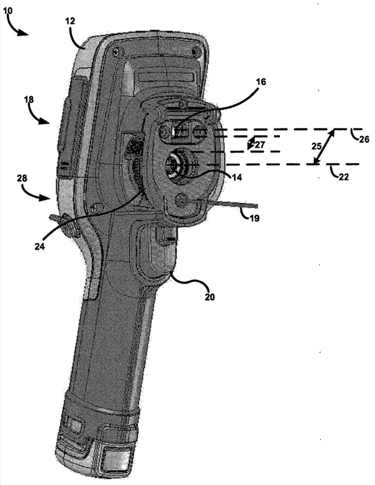
[0018] Thermal imaging cameras can be used to detect heat patterns throughout the observed scene. A thermal imaging camera detects infrared rays emitted by a scene and converts the infrared rays into an infrared image representing a thermal pattern. In some instances, thermal imaging cameras can also capture visible light from a scene and convert the visible light into a...


PUM


Abstract

A thermal imaging camera may be used to capture a visible-light (VL) image and an infrared (IR) image. In some examples, the camera includes adjustable focus IR optics. For example, the camera may include a focus mechanism coupled to the IR optics and configured to move the IR optics to various focus positions so as to focus the IR optics. The various focus positions may include a hyperfocal position in which a scene is in focus between a set distance and infinity, and a plurality of focus positions in which the scene is in focus between the set distance and a minimum focus distance. Depending on the configuration of the camera, the IR optics of the camera may define an F-number greater than 1.0, and an axis of the IR optics may be offset from an axis of the VL optics by a distance less than 1.7 inches.

Description

technical field [0001] The present invention relates to thermal imaging cameras, and more particularly to thermal imaging cameras with adjustable focal length infrared lenses. Background technique [0002] Thermal imaging cameras are used in a variety of settings. For example, thermal imaging cameras are often used to thermally inspect equipment during maintenance inspections. Illustrative equipment may include other types of equipment such as rotating machinery, switchboards, or banks of circuit breakers. Thermal inspections can detect equipment hotspots such as overheated mechanical or electrical components, helping to ensure timely repair or replacement of overheated equipment before more serious problems develop. [0003] Depending on the construction of the camera, thermal imaging cameras can also produce visible light images of the same object. The cameras can display infrared images as well as visible light images in a synergistic manner, for example to help operat...

Claims


Application Information

Patent Timeline
IPC IPC(8): H04N5/33G03B13/32G02B7/04
CPCH04N23/671H04N23/11
Inventor J·蔡J·T·皮克特J·M·希尔德B·布雷斯特
Owner JOHN FLUKE MFG CO INC
Why Eureka
Try Eureka