
Configuration management method of logical topology in virtual network and management server

A technology for managing servers and logical topologies, which is applied to the structural management of logical topologies of virtual networks and the field of managing servers, and can solve the problems of inability to grasp logical topology, expansion cannot be easily solved, and logical topology information cannot be generated.

Inactive Publication Date: 2013-04-10
HITACHI LTD
View PDF11 Cites 19 Cited by
  • Summary
  • Abstract
  • Description
  • Claims
  • Application Information

AI Technical Summary

Problems solved by technology

[0011] The problem with these existing technologies is that the logical topology information of the virtual network cannot be generated in a network environment using multiple virtualization technologies
[0012] In the technology disclosed in Patent Document 1, the target device is only a router for realizing VPN, and can generate topology information of a virtual router, but cannot generate topology information related to a virtual LAN.
In an office network or a data center network, virtual LAN is a commonly used technology, but there is a problem that the logical topology cannot be grasped in this technology
[0013] In the technology disclosed in Patent Document 2, the target device is only a switch or router that realizes VLAN. In an environment using virtual router technology, the problem is that the logical topology of the virtual network cannot be accurately grasped.
Also, the information that should be kept inside the generator in order to generate the logical topology is not disclosed
[0014] Therefore, in Patent Document 1 and Patent Document 2, there is a problem that logical topology information cannot be generated in a complex virtual network environment constructed by combining virtual LAN, virtual interface, virtual router technologies, etc.
Compared with the case of using a single virtualization technology, a virtual network using multiple virtualization technologies has more complex information to manage or corresponding information, and the above problems cannot be easily solved by simply expanding the existing technology. solve

Method used

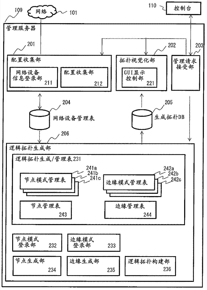
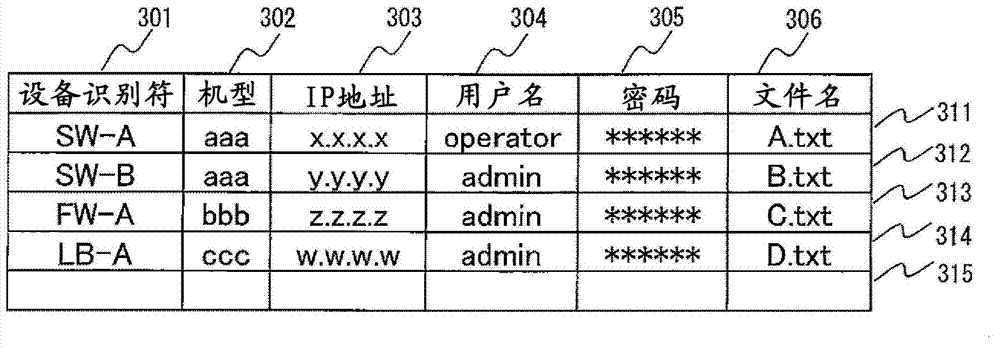

Image

  • Configuration management method of logical topology in virtual network and management server
  • Configuration management method of logical topology in virtual network and management server
  • Configuration management method of logical topology in virtual network and management server

Examples


Embodiment Construction

[0046] An embodiment is described by taking the logical topology generation in the network system in the data center as an example. In addition, a data center network is only one form of an application site, and the application destination includes a network spanning multiple data centers, a carrier network, an office network, or a campus network, and the like.

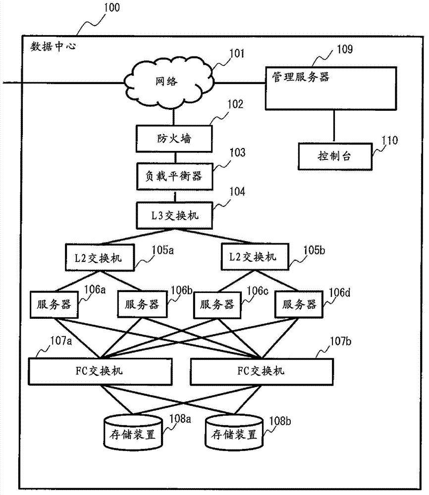
[0047] figure 1 It is a figure which shows an example of the system structure of this embodiment.

[0048] The data center 100 constitutes a system for providing appropriate ICT services via the network 101 . Devices that can serve as structural elements of this system include, in addition to network devices such as firewall 102, load balancer 103, L3 switch 104, and L2 switches 105a and 105b, server devices such as servers 106a, 106b, 106c, and 106d, and FCs. SAN (Storage Area Network) switch devices such as (Fibre Channel) switches 107a and 107b, and storage devices such as storage devices 108a and 108b. It is n...


PUM


Abstract

The present invention provides a configuration management method of a logical topology in a virtual network and a management server. Logical topology information of a virtual network is generated through the virtual network formed by virtualization technologies including virtual LAN, virtual interface and virtual router. (1) A configuration management in a management server is carried out such that setting patterns regarding creation of plural types of virtual resources and setting patterns regarding connection between the plural types of virtual resources are extracted from setting information of network devices configuring a virtual network by using plural types of virtualization technologies, (2) an ID required for creating a virtual resource and a connection relation between virtual resources are extracted from the extracted setting pattern, (3) an element corresponding to a virtual resource or a connection between a pair of virtual resources is created by using information including the extracted ID, and (4) the elements created from setting information of individual devices are aggregated to thereby create and store logical topology information representing a topology of the virtual network.

Description

technical field [0001] The present invention relates to a virtual network, a structure management server and a structure management method. Background technique [0002] In recent years, in the technical field of computer networking, a complex virtual network with various structures can be constructed by using a plurality of virtualization technologies in combination. [0003] Virtualization technology includes L2 (Layer 2) layer virtualization technology and L3 (Layer 3) layer virtualization technology. The virtualization technology of the L2 layer includes: virtual LAN (Local Area Network) technology such as VLAN (Virtual Local Area Network), and virtual interface technology such as VLAN interface or sub-interface. In addition, the virtualization technology of the L3 layer includes virtual router technologies such as VRF (Virtual Routing and Forwarding) and VR (Virtual Router). [0004] By using the virtual LAN technology or the virtual interface technology, for example,...

Claims


Application Information

Patent Timeline
Patent Type & Authority Applications(China)
IPC IPC(8): H04L12/24H04L12/46
CPCH04L41/22H04L12/4641H04L41/12H04L41/40H04L41/122
Inventor 肥村洋辅保田淑子中山真理子
Owner HITACHI LTD
Learn More