Clock supply device and method thereof

A clock supply and clock signal technology, applied in the direction of electrical components, automatic power control, etc., can solve the abnormal clock pulse of the phase-locked loop frequency multiplication, the noise becomes larger, and the duty cycle of the clock signal CLK is inaccurate, etc. problem, to achieve the effect of the best anti-interference ability

Inactive Publication Date: 2015-09-16
ALTEK CORP
View PDF2 Cites 0 Cited by
  • Summary
  • Abstract
  • Description
  • Claims
  • Application Information

AI Technical Summary

Problems solved by technology

However, if the amplitude of the voltage becomes smaller, the obvious disadvantage is that the noise becomes larger
Noise or jitter will cause the duty cycle of the clock signal CLK to be inaccurate
Therefore, under the framework of the typical electronic clock system 100, the frequency-multiplied clock output by the phase-locked loop 20 will be abnormal in order to save power.

Method used


Image

  • Clock supply device and method thereof
  • Clock supply device and method thereof
  • Clock supply device and method thereof

Examples


Embodiment Construction

[0074] Reference will now be made in detail to embodiments of the invention, examples of which are illustrated in the accompanying drawings. In addition, elements / members using the same reference numerals in the drawings and embodiments represent the same or similar parts.

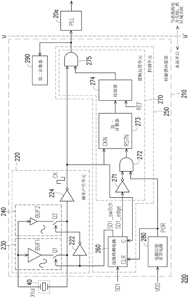
[0075] figure 2 is a schematic diagram of an electronic clock system 200 according to an embodiment of the present invention. Please refer to figure 2 . The electronic clock system 200 may include a clock supply apparatus (clock supply apparatus) 210 and a phase locked loop (Phase Locked Loop, PLL) 20a. The electronic clock system 200 can be applied to various electronic devices, such as digital still cameras (Digital Still Camera, DSC), mobile phones, but not limited thereto. The clock supply device 210 includes a frequency generating unit 220 and a control unit 250 . The frequency generating unit 220 includes a first driving unit 230 and a second driving unit 240 for controlling the first driving ...


PUM


Abstract

Disclosed are a clock pulse supply device and a method of the clock pulse supply device. The device comprises a frequency generating unit and a control unit. The frequency generating unit is used for responding a pattern signal to decide whether vibration amplitude of a clock pulse signal is first vibration amplitude or second vibration amplitude and converting an outer vibration signal to the clock pulse signal. The control unit receives the clock pulse signal and is used for responding a system status signal to output the pattern signal. When the control unit judges that the clock pulse signal is stable vibration, the clock pulse signal is supplied outside by the control unit. If the system status signal is a power-on signal, the first vibration amplitude is used as the vibration amplitude of the clock pulse signal. If the system status signal is a power-off signal, the second vibration amplitude which is smaller than the first vibration amplitude is used as the vibration amplitude of the clock pulse signal.

Description

technical field [0001] The present invention relates to an electronic clock technology, in particular to a clock supply device suitable for an electronic clock system and a method thereof. Background technique [0002] figure 1 is a schematic diagram of a typical electronic clock system 100 . Please refer to figure 1 . A general electronic device is configured with an electronic clock system 100 , and the electronic clock system 100 provides a clock signal CLK required by the electronic device to make the electronic device operate normally. The electronic clock system 100 includes a frequency generation module 10 , a phase locked loop (PLL) 20 , a counter 30 , a crystal oscillator 40 and a battery BAT. The electronic clock system 100 utilizes the quartz oscillator 40 and the frequency generating module 10 to generate a clock signal CLK of 32,768 Hz. The phase-locked loop 20 multiplies the frequency of the clock signal CLK for use by the circuits at the back end. The co...

Claims


Application Information

Patent Timeline
Patent Type & Authority Patents(China)
IPC IPC(8): H03L7/18
Inventor 陈岳彰
Owner ALTEK CORP
Why Eureka
Try Eureka