
Novel optical fiber type leakage detector used for direct-current converter valve

A DC converter valve and leak detector technology, which is applied in the application of light to test fluid tightness, etc., can solve the problem that the leak detector cannot identify the leakage flow, the valve tower cannot accurately monitor the water leakage, and the optical receiver has low identification power. and other problems, to achieve the effect of improving system reliability, low optical path attenuation rate, and strong anti-interference ability

Active Publication Date: 2013-04-10
STATE GRID CORP OF CHINA +2
View PDF5 Cites 8 Cited by
  • Summary
  • Abstract
  • Description
  • Claims
  • Application Information

AI Technical Summary

Problems solved by technology

However, the flat mirror reflective leak detection device has the following disadvantages: ①The optical cable probe is easily polluted when exposed to the air, resulting in false alarms; ②The leak detection device cannot identify the leakage flow rate, that is, it cannot report different signals according to the leakage situation, resulting in background control The water leakage of the valve tower cannot be accurately monitored
However, the detection cylinder float type leak detection device has the following disadvantages: ①The optical fiber detection system has no redundant configuration, and water leakage alarms caused by non-water leakage are prone to occur; ②The light attenuation of the leak detection device is large, and the optical transmitter needs to have a higher transmission power , the optical receiver needs to have a low recognition power; ③The leak detection device is prone to large attenuation of the optical path and false alarms after long-term operation, resulting in aging of the leak detection device and deterioration of the performance of the leak detection device; ④The large volume of the detection buoy makes the detection The overall volume of the drain device is large

Method used


Image

  • Novel optical fiber type leakage detector used for direct-current converter valve
  • Novel optical fiber type leakage detector used for direct-current converter valve
  • Novel optical fiber type leakage detector used for direct-current converter valve

Examples


Embodiment Construction

[0032] The technical solutions in the embodiments of the present application will be clearly and completely described below in conjunction with the drawings in the embodiments of the present application.

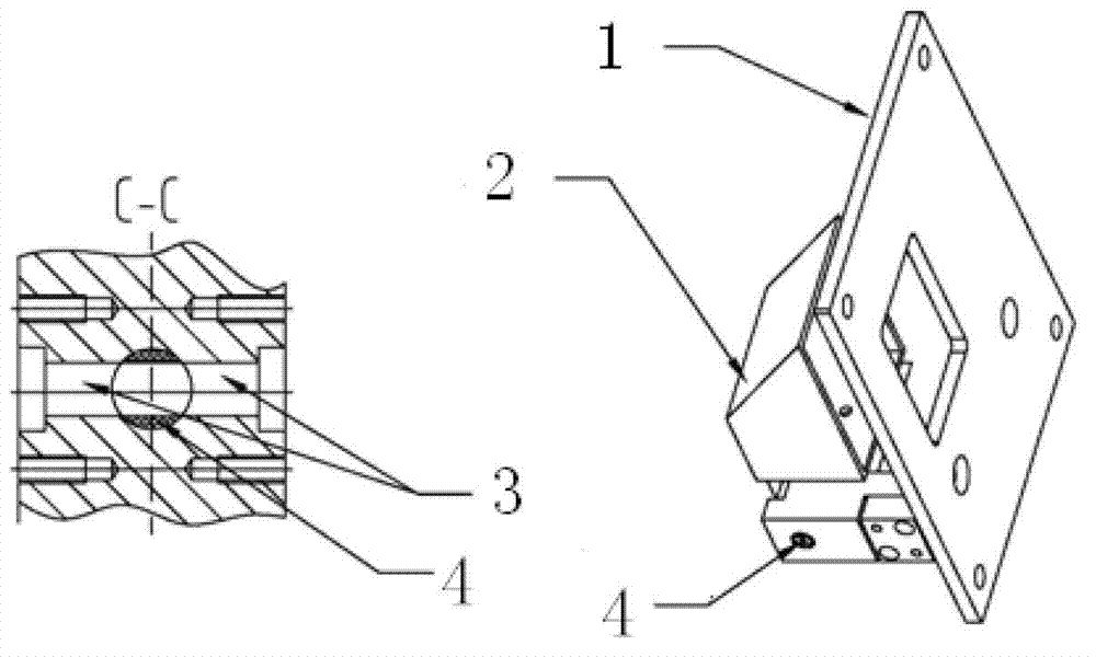
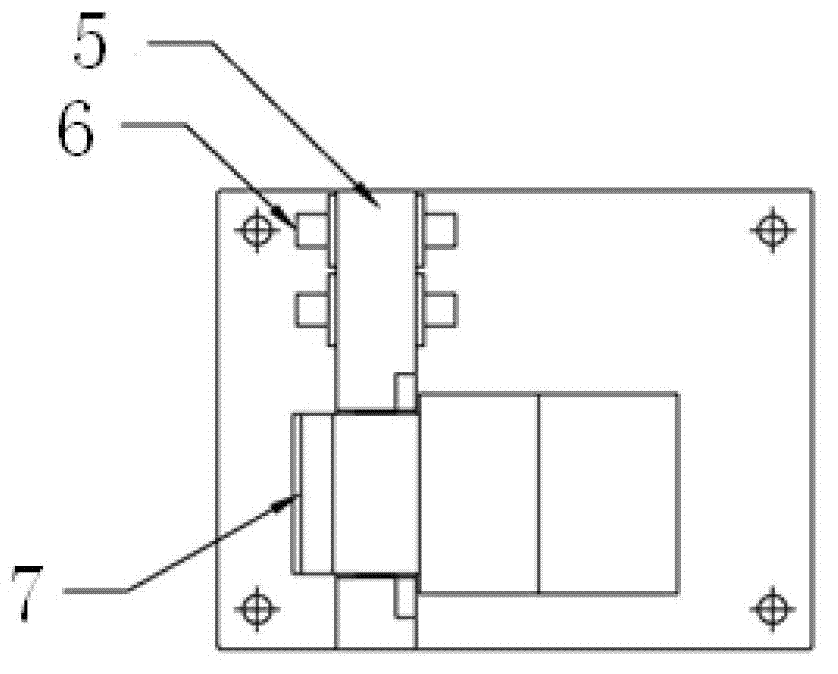
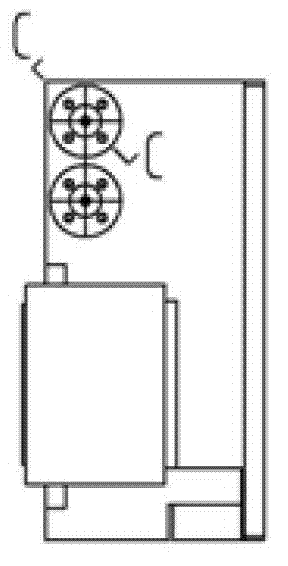
[0033] The invention provides an optical fiber leak detector for a direct current converter valve. The leak detector includes a liquid collector provided with a shielding metal plate at the bottom of the valve, a platform, a measuring piece and a leak detector; The collecting piece installed on the platform is connected with the leak detecting piece through an optical fiber; the collecting piece includes a bucket, a balance weight, a rotating shaft, and a collimating lens; the leak detecting piece includes a light emitting devices, photoreceivers, and valve-based electronics.

[0034] In this embodiment, the cooling liquid used by the converter valve is cooling water. see Figure 1-3 As shown, it shows the structural schematic diagram of the platform and the measuring piec...


PUM


Abstract

The invention provides an optical fiber type leakage detector used for a direct-current converter valve. The optical fiber type leakage detector comprises a liquid receiver provided with a valve base shielding mental plate, a platform, a volume collecting component and a leakage detecting component. The volume collecting component which is installed on the platform through a rack is connected with the leakage detecting component through the optical fiber. The volume collecting component comprises a tipping bucket, a balancing pouring weight, a rotating shaft and collimating lens. The leakage detecting component comprises an optical emitter, an optical receiver and valve base electrons. Compared with the prior art, the optical fiber type leakage detector used for the direct-current converter valve is simple in structure, high in measuring accuracy, low in optical attenuation rate and good in sealing performance.

Description

technical field [0001] The invention relates to an optical fiber leak detector, in particular to a novel optical fiber leak detector for DC converter valves. Background technique [0002] Since the valve tower of the diverter valve is equipped with a waterway system, the leakage of the waterway system will cause the components of the valve tower to be damaged, and the decrease in water cooling efficiency will cause the cooling effect of the electrical components of the entire valve tower to decrease. There is a water leakage detection device to detect water leakage, so as to realize the protection with the operation of the valve tower. [0003] There are mainly two types of leak detection devices used in the valve tower of the converter valve in the prior art: the plane mirror reflection type and the detection cylinder float type. The feature of the plane mirror reflection type leak detection device is that a plane mirror for water leakage detection is installed at the bott...

Claims


Application Information

Patent Timeline
IPC IPC(8): G01M3/38
Inventor 蓝元良周建辉林志光查鲲鹏栾洪州
Owner STATE GRID CORP OF CHINA
Learn More