Upright vacuum cleaner

A technology for vacuum cleaners and vacuum cleaners, applied in the directions of vacuum cleaners, suction hoses, cleaning equipment, etc., can solve the problems of heavy, bulky, and large cleaner heads, and achieve the effect of reducing material costs.

Inactive Publication Date: 2013-04-10
DYSON TECH LTD
View PDF6 Cites 2 Cited by
  • Summary
  • Abstract
  • Description
  • Claims
  • Application Information

AI Technical Summary

Problems solved by technology

It is generally not possible to use the main cleaner head for this purpose at all: the vacuum cleaner is mainly too heavy and bulky, and the cleaner head itself is too large

Method used


Image

  • Upright vacuum cleaner
  • Upright vacuum cleaner
  • Upright vacuum cleaner

Examples


Embodiment Construction

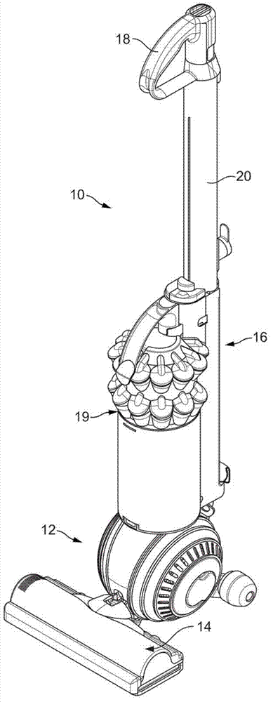
[0047] image 3 An upright vacuum cleaner 10 is shown.

[0048] The vacuum cleaner 10 has a rolling head assembly 12 which carries a stationary cleaner head 14 and a "upright" body 16 which is tiltable relative to the head assembly 12 and which includes a handle 18 for maneuvering the cleaner 10 over ground. In use, the user grasps the handle 18 and tilts the upright body 16 until the handle 18 is positioned at a height convenient for the user; the user can then use the handle 18 to roll the vacuum cleaner 10 over the ground to facilitate collecting dust on the ground or other debris. Dust and debris are drawn through a downwardly facing suction inlet on the cleaner head 14 by a motor-driven fan housed on the cleaner 10 . From here, the dust laden air stream is conveyed in conventional manner under the suction pressure generated by the fan to the cyclonic separation device 19 where the dust is separated from the air and the relatively clean air is then discharged back into ...


PUM


Abstract

An upright vacuum cleaner comprising a wand 22a fluidly connected to a separating apparatus on the cleaner via a hose 26 and which is used, as required, to clean above the level of the floor. The wand 22a is at least partly retractable inside the hose 26 for storage, and a hose catch 28 is provided at the end of the hose 26, this hose catch 28 being biased towards a locking position in which the hose catch 28 locks the wand 22a in an extended position. The hose 26 is a stretch hose arranged, in its coil-bound state, to act as a reaction member against which a user may readily force the biased hose catch 28 out of said locking position using the extended wand 22a. A manual release button is also provided.

Description

technical field [0001] The present invention generally relates to an upright vacuum cleaner, including dry, wet, or "wet and dry" upright vacuum cleaners. Background technique [0002] Upright vacuum cleaners typically have a rolling head assembly that carries a fixed cleaner head in a plane that is in parallel contact with the floor surface. The head assembly is mounted on an inclined "upright" body which carries a handle at its upper end. In regular floor cleaning mode, the user tilts the "upright" body until the handle is at a convenient height, then uses the handle to manually propel the cleaner across the floor, keeping the cleaner head in a plane of contact parallel to the floor surface. [0003] Vacuum cleaning above ground level is often desired. For example, it may be desirable to vacuum clean a shelf, a staircase, or an upper corner of a room. It is generally not at all possible to use the main cleaner head for this purpose: the vacuum cleaner is mainly too heav...

Claims


Application Information

Patent Timeline
Patent Type & Authority Applications(China)
IPC IPC(8): A47L5/32A47L9/24A47L9/00
CPCA47L9/248A47L9/244A47L5/32A47L9/242
Inventor A.J.威尔斯P.A.麦克勒基C.E.帕克J.戴森P.D.甘麦克
Owner DYSON TECH LTD
Why Eureka
Try Eureka