Combination clamp for flat connection terminals and cables

A terminal and cable technology, applied in the direction of circuits, connections, electrical components, etc., can solve the problems of easy loosening of screws, short service life, small contact surface, etc., and achieve stable and reliable connection, convenient and safe use, and small contact resistance Effect

Active Publication Date: 2013-04-03
GUANGZHOU PANYU CABLE WORKS
View PDF6 Cites 7 Cited by
  • Summary
  • Abstract
  • Description
  • Claims
  • Application Information

AI Technical Summary

Problems solved by technology

[0002] The existing clamps are unevenly stressed on one side and easily deformed on one side. When the nut is tightened, it will slide to the left and right sides. It takes multiple adjustments to align, which increases the difficulty of operation; it cannot be self-locking, and the connection is not stable. Affected by thermal expansion and contraction, easy to loosen, short service life, frequent maintenance; small contact surface, requires professional tools, inconvenient installation, poor versatility
The connection between the cable and the terminal is not firm and easy to loosen

Method used


Image

  • Combination clamp for flat connection terminals and cables
  • Combination clamp for flat connection terminals and cables

Examples


Embodiment 1

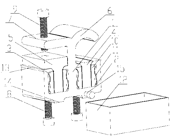
[0019] A flat terminal and cable combination clip, including a clip body 1, characterized in that: the clip body 1 is provided with a first groove 2 and a second groove 3, the first groove 2 and the second groove The first movable chuck 4 and the second movable chuck 5 that can move up and down are respectively embedded in the groove 3, and the top of the clamp body 1 is fixedly connected with the first movable chuck 4 and the second movable chuck 5 respectively. The first static chuck 6 and the second static chuck 7 are provided with two bolt holes under the clamp body 1, and while the two adjusting bolts 8 pass through the two bolt holes and are fixedly connected with the wire clamp body 1, they are connected with the clamp body 1 respectively. The first movable chuck 4 and the second movable chuck 5 abut against each other. Wherein the first movable chuck 4 and the first static chuck 6 are the clamping parts, and the two are in the structure of the inner circular arc surfac...

Embodiment 2

[0021] On the basis of embodiment 1, this embodiment has been improved as follows:

[0022] One or both sides of the first movable chuck 4 and / or the second movable chuck 5 are provided with anti-return serrations that are reversed downward, and the anti-reverse serrations of the first movable chuck 4 and the second movable chuck 5 The anti-loosening anti-reversal sawtooth sheet 10 matched with it is provided on the outer side of the outer side, and the anti-loosening and anti-reversal sawtooth sheet 10 on at least one side of the first movable chuck 4 and the second movable chuck 5 is provided between the clamp body 1. Stage clip 11 is arranged, and movable collet and anti-loosening anti-reverse sawtooth sheet 10 are compressed by stage clip 11. Wherein the compression spring 11 is a wave-shaped leaf spring or a columnar spring, and the columnar spring can be a cylindrical helical spring, preferably a leaf spring. The difference between the disassembly and the first embodime...


PUM


Abstract

The invention discloses a combination clamp for flat connection terminals and cables. The combination clamp comprises a wire clamp body, and is characterized in that a first groove and a second groove are arranged in the wire clamp body, a first movable clamping head and a second movable clamping head which can move up and down are respectively embedded in the first groove and the second groove, a first fixed clamping head and a second fixed clamping head which are respectively opposite to the first movable clamping head and the second movable clamping head are fixedly connected to the upper side of the wire clamp body, two bolt holes are arranged on the lower side of the wire clamp body, and two adjusting bolts are respectively abutted to the first movable clamping head and the second movable clamping head while penetrating through the two bolt holes to be fixedly connected with the wire clamp body. The combination clamp for the flat connection terminals and the cables is high in universality, is applicable to the cables with various wire diameters, is simple in structure, reasonable in design and firm and reliable in connection, and can be used conveniently and safely, the pressure is balanced, clamping force is constant, and contact resistance is low.

Description

technical field [0001] The invention relates to a clamp, in particular to a clamp combined with a flat terminal and a cable. Background technique [0002] The existing clamps are unevenly loaded on one side and easily deformed on one side. When the nut is tightened, it will slide to the left and right sides. It requires multiple adjustments to align, which increases the difficulty of operation; it cannot be self-locking, and the connection is not stable. Affected by thermal expansion and contraction, it is easy to loosen, has a short service life and frequent maintenance; the contact surface is small, professional tools are required, installation is inconvenient, and the versatility is poor. The connection between the cable and the terminal is not firm, and it is easy to loosen. Contents of the invention [0003] The task of the present invention is to provide a cable clamp with strong versatility, suitable for cables with different wire diameters, convenient wiring, reli...

Claims


Application Information

Patent Timeline
Patent Type & Authority Applications(China)
IPC IPC(8): H01R11/14H01R4/40H01R4/44H01R4/48
Inventor 胡超强尤占山覃丹王利江卢广业张仕宽申常伟
Owner GUANGZHOU PANYU CABLE WORKS
Why Eureka
Try Eureka