A multi-step porcelain tube and a gas discharge tube made of the multi-step porcelain tube

A gas discharge tube and multi-step technology, which is applied to overvoltage arresters, circuits, and electrical components using spark gaps, can solve problems such as high voltage protection level, melting of built-in electrode pieces, increased arc voltage and freewheeling capacity, etc. Achieve the effect of increasing the creepage distance between the gaps, enhancing the freewheeling capability, and increasing the arc voltage

Active Publication Date: 2016-09-28
EPCOS ELECTRONICS XIAOGAN
View PDF6 Cites 0 Cited by
  • Summary
  • Abstract
  • Description
  • Claims
  • Application Information

AI Technical Summary

Problems solved by technology

[0003]1. The voltage protection level is higher than 3000V;
[0004]2. The performance is unstable during the service life, and the open gap is easily affected by the climate environment and pollution;
[0005]3. There are splashing flames or shock waves during work;
[0006]4. There are installation distance requirements with peripheral devices or equipment;
[0007]5. Additional trigger lines are required, and the arc is extinguished by auxiliary devices
However, from the actual effect, the problem of side discharge between the gaps is still unavoidable, and the increase in arc voltage and freewheeling capacity is limited, so it cannot be widely used.
[0009] Typical product 1: Internal structure such as Figure 3 shows that there are 16 discharge gaps in the middle layer of the discharge tube, but the arc voltage is only 48V, and the discharge is from the side under high current conditions, causing the edges of the built-in electrodes to heat up and melt together fail
[0010]Typical product 2: internal structure such as Figure 4 shows that there are three discharge gaps in the single-layer discharge tube, but the arc voltage is only 42V. Under the condition of high current, the middle gap discharges from the middle, and the other two gaps are due to insufficient creepage distance. Then discharge from the edge (side) of the electrode, causing the edge of the built-in electrode sheet to heat up and melt together to fail

Method used


Image

  • A multi-step porcelain tube and a gas discharge tube made of the multi-step porcelain tube
  • A multi-step porcelain tube and a gas discharge tube made of the multi-step porcelain tube
  • A multi-step porcelain tube and a gas discharge tube made of the multi-step porcelain tube

Examples


Embodiment Construction

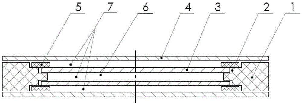
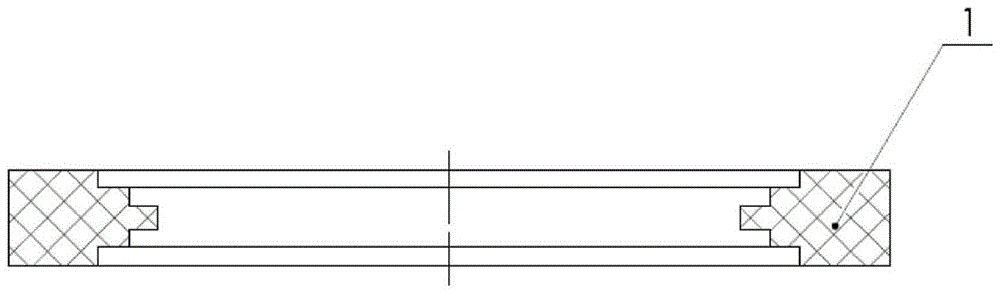
[0022] Such as figure 1 As shown, a multi-step porcelain tube includes a porcelain tube body 1, and a plurality of steps 2 are arranged inside the porcelain tube body 1.

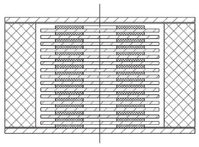
[0023] A multi-layer gas discharge tube, a first discharge electrode 3 and a second discharge electrode 4 are arranged on the step 2 of the multi-step porcelain tube, and an isolating ceramic sheet 5 is arranged between the first discharge electrode 3 and the second discharge electrode 4, The cavity 6 formed by the two second discharge electrodes 4 and the porcelain body 1 is filled with inert and non-inert mixed gas, and a three-layer discharge gap 7 is formed.

[0024] When using the present invention as a protective device, the arc voltage is increased by connecting multilayer discharge tubes in series, thereby cutting off freewheeling. The protective device includes n gas discharge tubes, which are welded together under the condition of 850 degrees by brazing. There are 3 discharge gaps in each layer o...


PUM


Abstract

A multi-step porcelain tube and a multi-layer gas discharge tube, a first discharge electrode and a second discharge electrode are arranged on the steps of the multi-step porcelain tube, and an insulating ceramic sheet is arranged between the first discharge electrode and the second discharge electrode. Inert gas is filled in the cavity formed by the first discharge electrode, the second discharge electrode and the insulating ceramic sheet. The multi-step porcelain tube and the gas discharge tube made of the multi-step porcelain tube provided by the present invention effectively increase the creeping distance between the gaps and avoid the edge discharge between the gaps, thereby ensuring There are three independent discharge gaps in the single-layer discharge tube, which doubles the arc voltage. The single-layer arc voltage reaches 65V, and the freewheeling ability is greatly enhanced.

Description

technical field [0001] The patent of the present invention relates to a gas discharge tube used in lightning strike protection for power supply systems. Background technique [0002] With approximately twice as many thunderstorms recorded today as there were a decade ago, protecting people and electrical equipment from voltage surges has become all the more important. In this field, in addition to protecting human life, more technical solutions focus on ensuring the good and continuous operation of electrical installations. Based on the lightning protection zone principle of the fourth part of VDE V 0185, IEC 61643-11 has made specifications for gas discharge tubes in sub-distribution networks (level II) and terminals (level III) and building entrances (level I) . Gas discharge tubes have long been widely used for protection of equipment, sub-distribution networks, and neutral-to-earth (NPE) protection at building entrances. Since the protection of the live line at the en...

Claims


Application Information

Patent Timeline
Patent Type & Authority Patents(China)
IPC IPC(8): H01T4/12H01T4/16H01T4/20
Inventor 张玉T·费斯特博刘兵洪家平
Owner EPCOS ELECTRONICS XIAOGAN
Why Eureka
Try Eureka