
Fractional combustion chamber

A combustion chamber and fuel technology, applied in the direction of combustion chambers, continuous combustion chambers, combustion methods, etc., can solve problems such as unfavorable outlet temperature distribution uniformity, unfavorable reliability and weight loss of the combustion chamber, complex structure of the combustion chamber, etc., to achieve Fuel and air are mixed evenly, the outlet temperature distribution characteristics are improved, and the effect of suppressing local hot spots

Inactive Publication Date: 2013-04-03
成都中科航空发动机有限公司
View PDF4 Cites 22 Cited by
  • Summary
  • Abstract
  • Description
  • Claims
  • Application Information

AI Technical Summary

Problems solved by technology

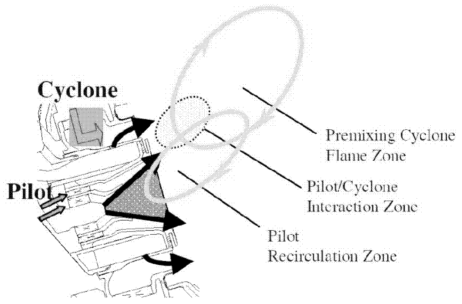
The TAPS combustion chamber adopts the strategy of split head air intake and oil supply, and the torch-shaped flame form generated by its combustion is easy to cause local high temperature at the outlet, which is not conducive to the uniformity of outlet temperature distribution;
[0008] (3) The head of the TAPS combustion chamber adopts a three-stage swirler structure, and there are complicated oil supply pipelines, cooling air passages, and air passages for blowing off carbon deposits, resulting in a very complicated structure of the combustion chamber, which affects the reliability of the combustion chamber. Detrimental effects on sex and weight loss

Method used


Image

  • Fractional combustion chamber
  • Fractional combustion chamber
  • Fractional combustion chamber

Examples


Embodiment Construction

[0039] In order to make the object, technical solution and advantages of the present invention clearer, the present invention will be described in further detail below in conjunction with specific embodiments and with reference to the accompanying drawings.

[0040] It should be noted that, in the drawings or descriptions of the specification, similar or identical parts all use the same figure numbers. Implementations not shown or described in the accompanying drawings are forms known to those of ordinary skill in the art. Additionally, while illustrations of parameters including particular values ​​may be provided herein, it should be understood that the parameters need not be exactly equal to the corresponding values, but rather may approximate the corresponding values ​​within acceptable error margins or design constraints. In addition, the directional terms mentioned in the following embodiments, such as "upper", "lower", "front", "rear", "left", "right", etc., are only re...


PUM


Abstract

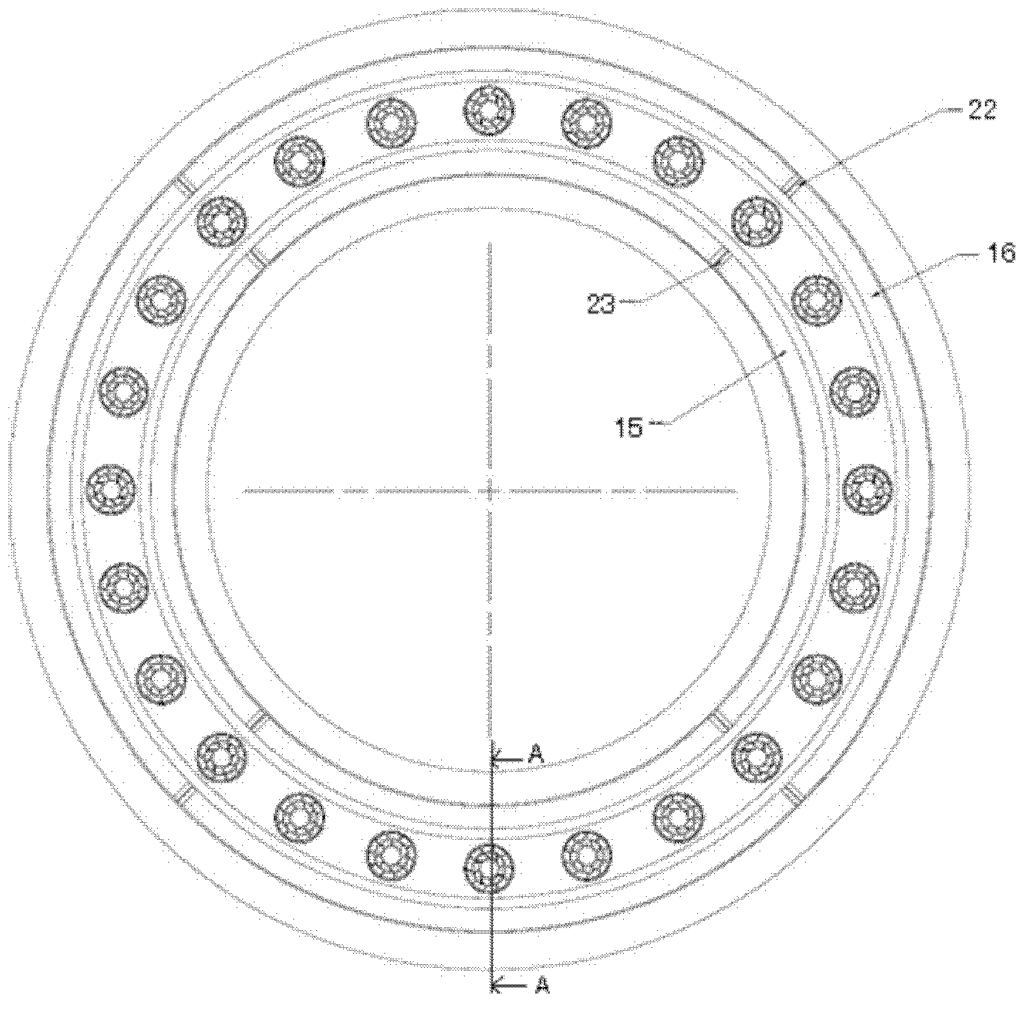
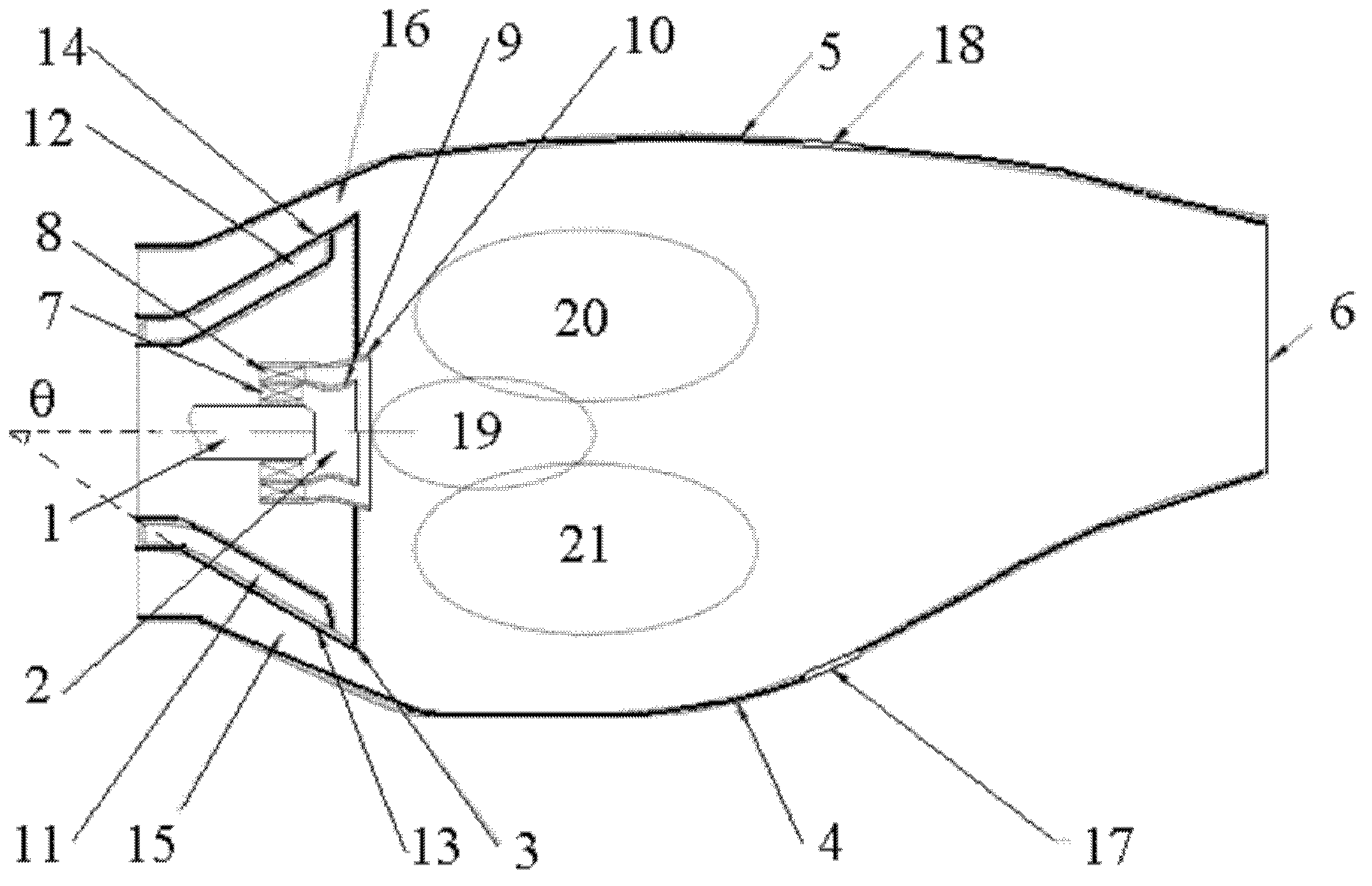
The invention provides a staged combustion chamber. The staged combustion chamber comprises an annular flame barrel and a main combustion stage assembly, wherein the annular flame barrel comprises a flame barrel inner ring and a flame barrel outer ring which are coaxial with each other; the front section of the annular flame barrel is in the form of a cone of which the inner diameter is increased gradually; and the main combustion stage assembly is positioned at the front section of the annular flame barrel, is used for providing fuel and air needed by combustion of a main combustion stage, and comprises an annular bluff body, an inner / outer ring oil cavity a plurality of duty stage assemblies; the inner ring surface of the annular bluff body constructs an inner ring air flow channel together with the inner surface of the flame barrel inner ring and the outer ring surface of the annular bluff body constructs an outer ring air flow channel together with the inner surface of the flame barrel outer ring; the inner / outer ring oil cavity is attached to the inner / outer side of the annular bluff body and by the inner / outer ring oil cavity, accommodated fuel can be ejected onto the inner ring air flow channel through a plurality of inner ring ejection holes positioned in the inner / outer ring surface of the annular bluff body; and the plurality of duty stage assemblies which are positioned in a space encircled by the annular bluff body. In the staged combustion chamber provided by the invention, main combustion stage air enters the combustion chamber in a full ring air inlet way, so that the pressure loss of the combustion chamber is reduced, and the fuel consumption of an engine is lowered.

Description

technical field [0001] The invention relates to the field of low-pollution combustors of aero-engines, in particular to a staged combustor for direct injection of main combustion stage air full-circle intake fuel. Background technique [0002] In order to meet the requirements that the civil large duct is more economical, more environmentally friendly and safer than the turbofan engine, the combustion chamber of the aero-engine is required to have a small pressure loss, uniform outlet temperature distribution, and pollutants, especially NO x Low emissions. Combustion chamber NO x The level of production is closely related to the flame temperature in the combustion zone, and the temperature in the combustion zone exceeding 1800K will cause NO x Due to the diffusion combustion method used in the head of the conventional combustion chamber, the equivalent ratio of the combustion zone is close to 1, and the temperature of the combustion zone is close to the temperature of the ...

Claims


Application Information

Patent Timeline
Patent Type & Authority Applications(China)
IPC IPC(8): F23R3/52F23R3/38
Inventor 杨金虎毛艳辉刘富强刘存喜穆勇徐纲朱俊强
Owner 成都中科航空发动机有限公司
Learn More