Adjusting device of variable valve lift mechanism and variable valve lift mechanism

A valve lift and adjustment device technology, applied in valve devices, machines/engines, mechanical equipment, etc., can solve problems such as increasing the height of the engine, and achieve the effect of fewer parts, easy processing and reliable contact

Inactive Publication Date: 2015-02-04
GREAT WALL MOTOR CO LTD
View PDF10 Cites 1 Cited by
  • Summary
  • Abstract
  • Description
  • Claims
  • Application Information

AI Technical Summary

Problems solved by technology

The existing variable valve lift mechanisms on the market include BMW's Valvetronic, Porsche's Variocam, Honda's VTEC, Nissan's VVEL, Toyota's Valvematic, Delphi's CVVL, etc. These existing technologies are basically achieved by changing the driving cam mechanism. Change the valve lift curve, so as to add more parts and ensure higher machining accuracy, and at the same time increase the height of the engine to a certain extent

Method used


Image

  • Adjusting device of variable valve lift mechanism and variable valve lift mechanism
  • Adjusting device of variable valve lift mechanism and variable valve lift mechanism
  • Adjusting device of variable valve lift mechanism and variable valve lift mechanism

Examples


Embodiment 1

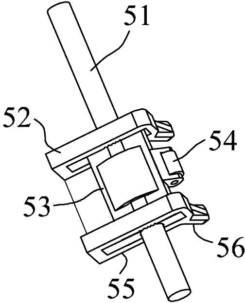
[0023] Such as figure 1 As shown, this embodiment discloses an adjusting device for a variable valve lift mechanism, which is arranged between the cam mechanism and the valve mechanism of the variable valve lift mechanism, and includes a main body 52, a driving mechanism and an external force bearing part. The main body 52 has a first force applying portion 55 and a second force applying portion 56, the second force applying portion 56 is in contact with the first force applying portion 55 and extends obliquely downward, the main body 52 has the first force applying portion 55 alone in contact with the valve mechanism, and a second state in which the second biasing portion 56 is in contact with the valve mechanism alone.

[0024] The driving device applies a rotational driving force to the main body 52, so that the main body 52 can switch back and forth between the first state and the second state. In this embodiment, the driving device specifically includes a rotating shaft 5...

Embodiment 2

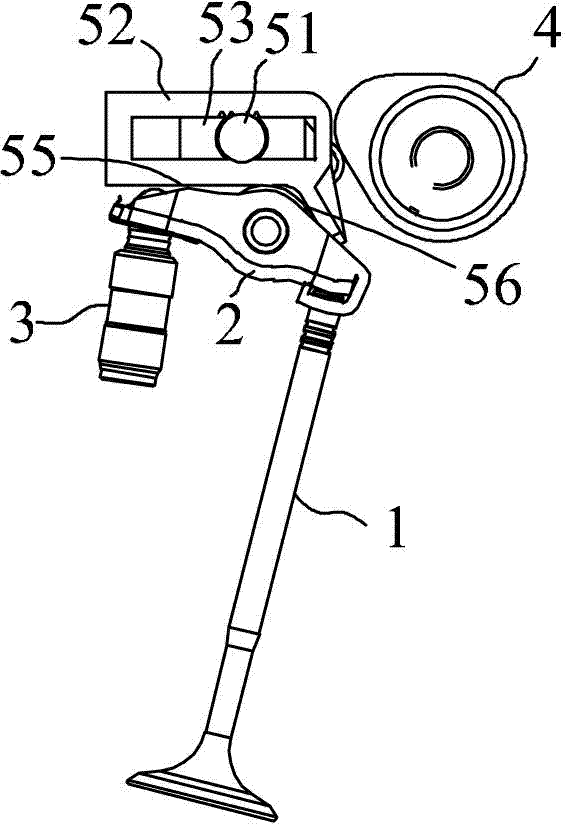
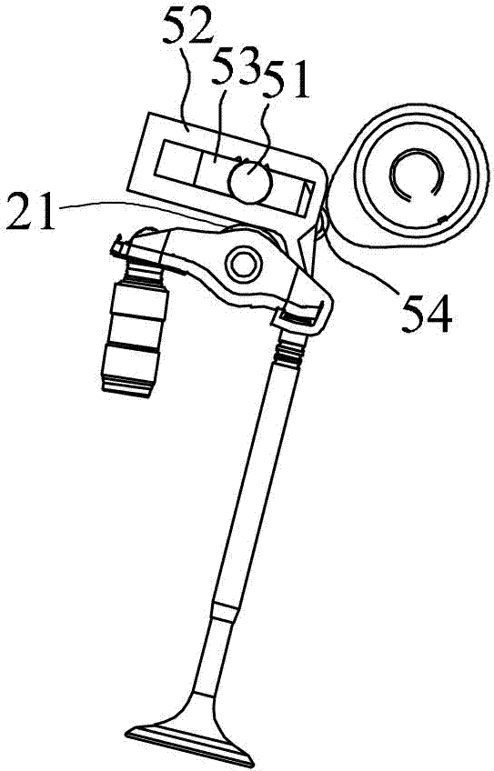
[0027] Such as figure 2 and image 3 As shown, this embodiment discloses a variable valve lift mechanism, including a valve mechanism and a cam mechanism 4. The valve mechanism includes a valve 1, a rocker arm 2 connected to the valve 1, and a hydraulic tappet 3 supporting the rocker arm 2. The rocker arm 2 is provided with a roller 21, the above is the existing structure of the well-known engine, it also includes the adjusting device of the variable valve lift mechanism of the first embodiment, the roller 21 can be connected with the first force applying part 55 Or the second force applying portion 56 contacts, and the cam mechanism 4 contacts the roller 54 , and when the cam mechanism 4 rotates, the roller 54 is pressed down, so that the main body 52 rotates. The angle between the line connecting the axis of the rotating shaft 51 and the roller 21 relative to the line connecting the axis of the rotating shaft 51 and the cam mechanism 4 is 60°-80°, which can ensure the reli...


PUM


Abstract

The invention relates to an engine gas intake mechanism, in particular to a variable valve lift mechanism, and also relates to an adjusting mechanism of the variable valve lift mechanism. The adjusting mechanism of the variable valve lift mechanism is arranged between a cam mechanism and a valve mechanism of the variable valve lift mechanism; the adjusting mechanism of the variable valve lift mechanism comprises a main body, a driving mechanism and an external-force bearing part, wherein the main body is driven by the driving mechanism to move, so that the contact between the main body and the valve mechanism is changed and the contact between a first force applying part or a second force applying part and the valve mechanism is changed; therefore, the valve lift is changed, the structure is simple, less parts are needed and the height of an engine cannot be obviously increased.

Description

technical field [0001] The invention relates to an engine intake mechanism, in particular to a variable valve lift mechanism, and also relates to an adjusting device for the variable valve lift mechanism. Background technique [0002] Variable valve lift technology is used to reduce engine fuel consumption, improve emission levels, and take into account the low-speed and high-speed characteristics of the engine, etc., which is of great significance. The existing variable valve lift mechanisms on the market include BMW's Valvetronic, Porsche's Variocam, Honda's VTEC, Nissan's VVEL, Toyota's Valvematic, Delphi's CVVL, etc. These existing technologies are basically achieved by changing the driving cam mechanism. Changing the valve lift curve will add more parts and ensure higher machining accuracy, while increasing the height of the engine to a certain extent. Contents of the invention [0003] In order to solve the deficiencies in the prior art, the present invention provi...

Claims


Application Information

Patent Timeline
Patent Type & Authority Patents(China)
IPC IPC(8): F01L13/00
Inventor 刘亚奇高定伟刘刚宋清哲
Owner GREAT WALL MOTOR CO LTD
Why Eureka
Try Eureka