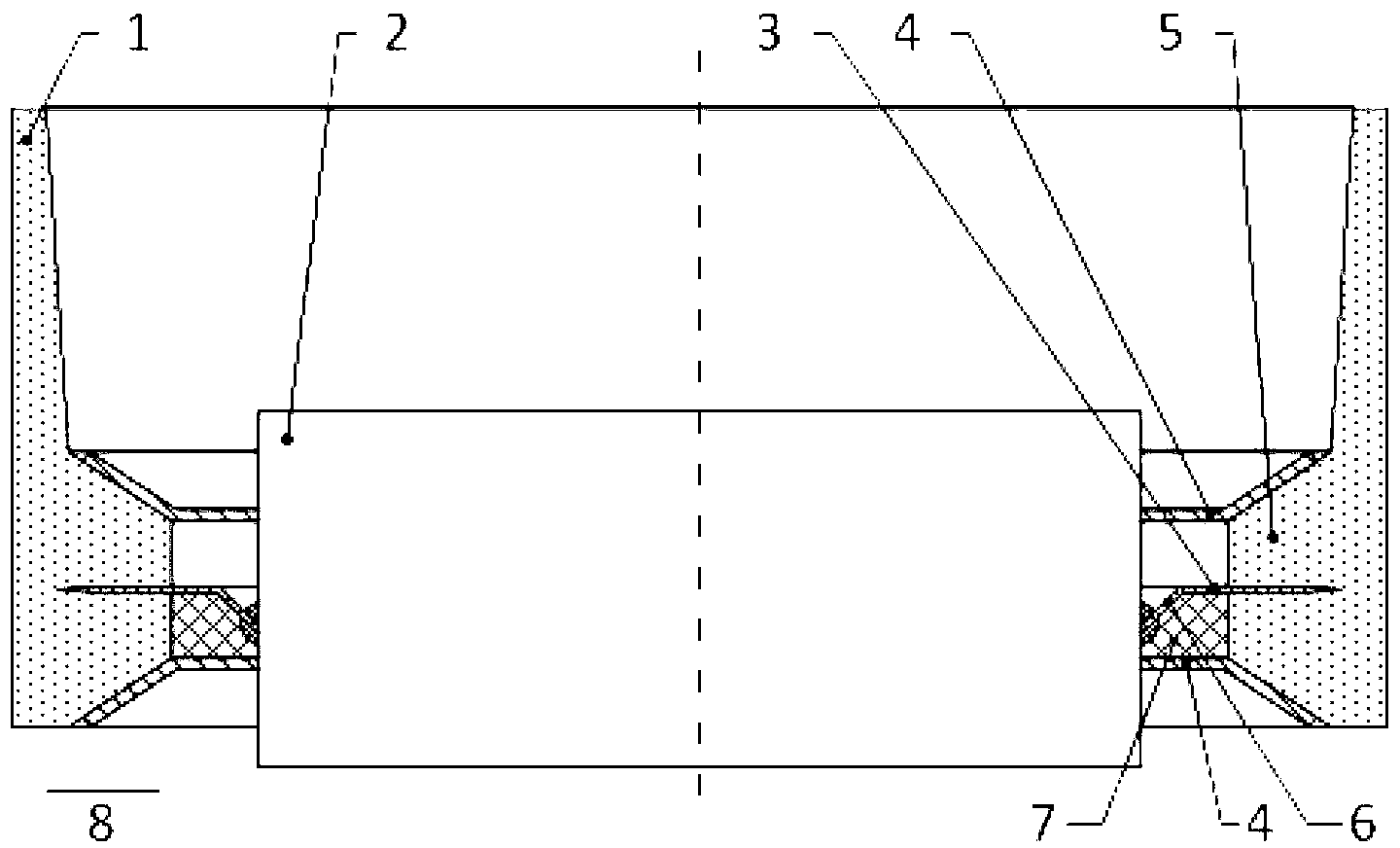
Thin-film sealing-in structure of high-temperature-resistant and high-strength glass tube and metal piece

A metal film and glass tube technology, applied in the field of glass and metal sealing structure, can solve the problems of easy damage of metal film, insufficient compact size, difficult processing, etc., and achieve the effect of reduced parts, compact structure and strong versatility

Inactive Publication Date: 2013-04-03
NANJING XUCHENG NEW ENERGY TECH
View PDF5 Cites 3 Cited by
  • Summary
  • Abstract
  • Description
  • Claims
  • Application Information

AI Technical Summary

Problems solved by technology

[0003] Purpose of the invention: The purpose of the invention is to provide a high-temperature-resistant, high-strength film sealing structure between glass tubes and metal parts to solve the problems of other sealing schemes such as complex structure, difficult processing, not compact enough size, and easy damage to the metal film.

Method used


Image

  • Thin-film sealing-in structure of high-temperature-resistant and high-strength glass tube and metal piece
  • Thin-film sealing-in structure of high-temperature-resistant and high-strength glass tube and metal piece
  • Thin-film sealing-in structure of high-temperature-resistant and high-strength glass tube and metal piece

Examples


Embodiment Construction

[0024] The present invention will be further explained below in conjunction with the accompanying drawings.

[0025] Such as figure 1 As shown, a kind of high-strength glass tube and metal film sealing structure of the present invention, it comprises glass tube 1 and metal film ring 3, and described metal film ring 3 comprises annular surface, and the ring shape of metal film ring 3 The surface is welded and fixed in the tube wall of the glass tube 1, that is, the annular surface of the metal film ring 3 and the glass frit are welded at high temperature in a mold that is shaped like the glass tube 1, and the outer diameter of the glass tube 1 is larger than that of the metal film ring 3. The outer diameter of the surface, that is, the annular surface of the metal film ring 3 is clamped inside the glass tube 1, and the two form an airtight seal.

[0026] Such as figure 2 As shown, since the thermal expansion coefficients of the glass tube 1, the metal part 2 and the metal fi...


PUM


Abstract

The invention discloses a thin-film sealing-in structure of a high-temperature-resistant and high-strength glass tube and a metal piece. The annular face of a metal thin film ring is fixedly welded on the wall of the glass tube; an internal diameter of the metal thin film ring is less than an internal diameter of the glass tube; an external diameter of the metal thin film ring is less than an external diameter of the glass tube; the outer surface of the metal piece is fixedly arranged on the inner lateral face of the metal thin film ring; two bumps with the inclination face are arranged on the wall at which the glass tube is welded with the metal thin film ring; supporting rings are respectively arranged at the positions of the bumps; each supporting ring comprises an annular face with an internal diameter adaptive with an outer diameter of the metal piece; the inner lateral faces of the annular faces of the supporting rings and the outer lateral face of the metal piece are fixed; the annular faces of the supporting rings are further connected with slope faces formed by extending and bending outward; the slope faces are adaptive with the inclination faces of the dumps on the glass tube; the inclination faces are oppositely arranged; and the slopes faces of the two supporting rings are respectively matched with the inclination faces. The thin-film packaging structure provided by the invention has the characteristics of good high-temperature resistance, high strength, compact size, convenience in machining, low cost and strong generality.

Description

technical field [0001] The invention relates to a new type of sealing structure between glass and metal, specifically a film sealing structure of high temperature resistance and high strength glass tube and metal parts, which can be applied to metal and glass for sealing and in Products used at high temperatures, such as electronic tubes, lighting fixtures, solar vacuum collectors, etc. Background technique [0002] There are many sealing methods for glass and metal, but there are not many sealing methods that can be applied to high temperature environments. Among them, the film sealing method has better high temperature resistance, but there are problems that the film is easily oxidized and has low strength at high temperature. For example, the product described in the patent No. 201010528354.5 "A Straight-through Solar Vacuum Heat Collector" adopts a film sealing method, but its reinforcement structure is complicated, the glass tube is easily cracked at high temperature, a...

Claims


Application Information

Patent Timeline
IPC IPC(8): C03C27/02
CPCC03C27/02
Inventor 黄锋
Owner NANJING XUCHENG NEW ENERGY TECH
Why Eureka
Try Eureka