
Vertical lifting device

A vertical lifting and hinged technology, applied in the direction of lifting devices, lifting frames, etc., can solve problems such as complex structure, failure to meet production requirements, poor stability, etc., and achieve the effects of simplified equipment structure, strong lifting load capacity, and reduced impact

Active Publication Date: 2013-04-03
ANHUI JEE AUTOMATION EQUIP CO LTD
View PDF9 Cites 11 Cited by
  • Summary
  • Abstract
  • Description
  • Claims
  • Application Information

AI Technical Summary

Problems solved by technology

Due to the structure of the conveying equipment itself and the requirements of the conveying weight, the reciprocating conveying equipment powered by cylinders for lifting and balancing has disadvantages such as poor stability and complex structure, which cannot meet production requirements.

Method used


Image

  • Vertical lifting device
  • Vertical lifting device
  • Vertical lifting device

Examples


Embodiment Construction

[0019] The structure of the vertical lifting device in the present embodiment is set to:

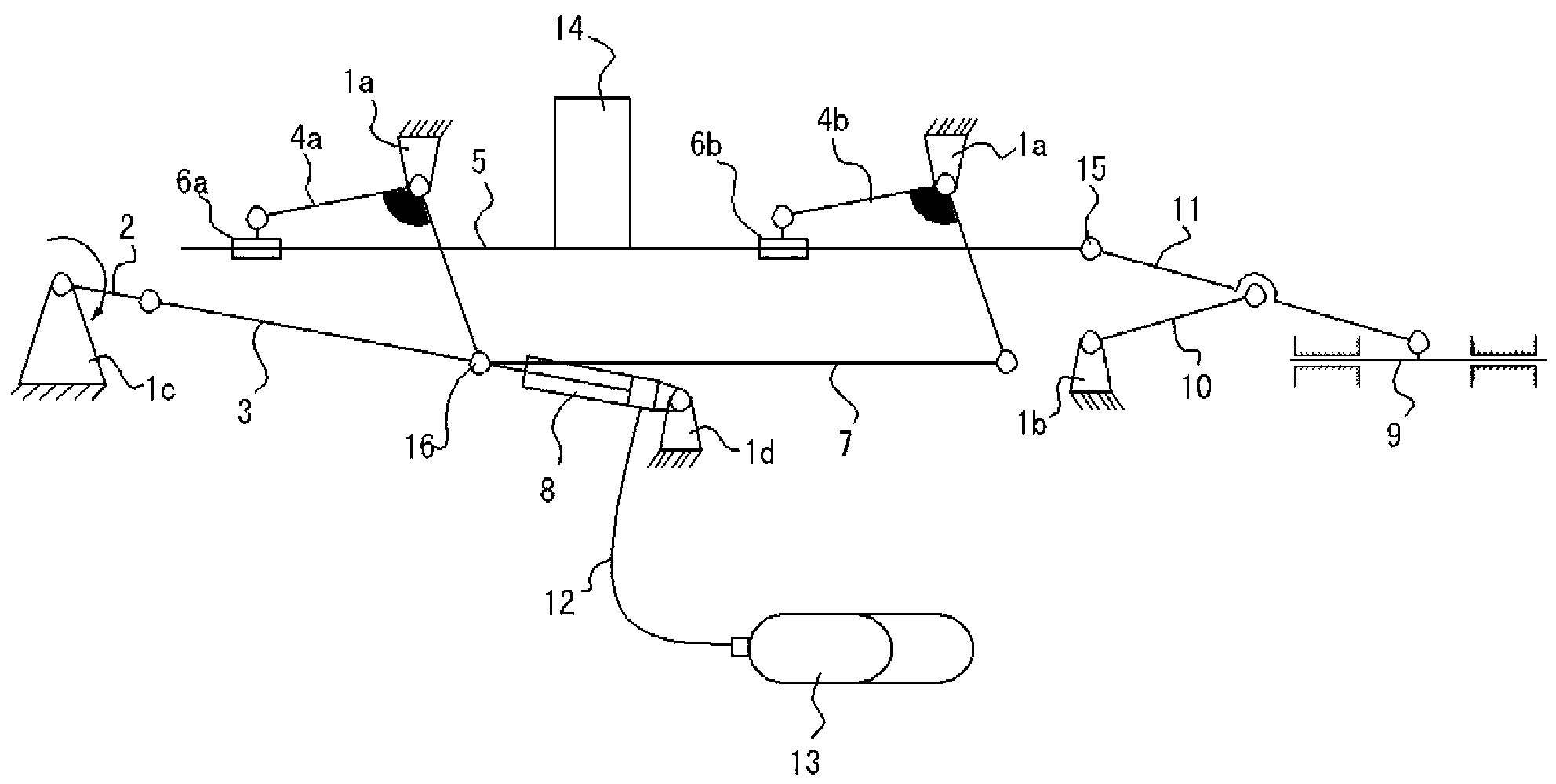
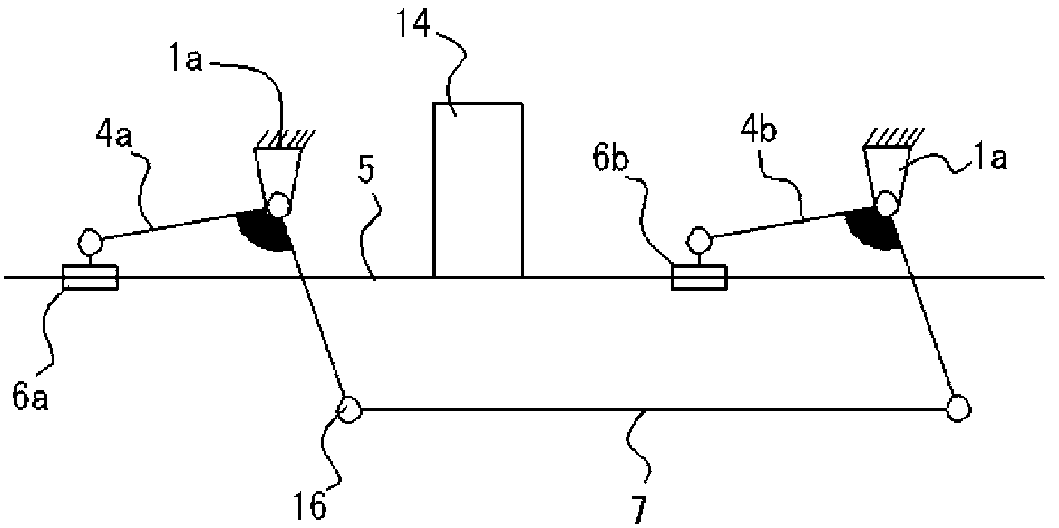
[0020] Such as figure 1 and figure 2 As shown, a parallelogram transmission mechanism is set, including: respectively hinge the first rocker 4a and the second rocker 4b on the top frame 1a on both sides; 7 connection, the outer rod ends of the first rocker 4a and the second rocker 4b are respectively provided with the first slider 6a and the second slider 6b at the same height, the first slider 6a and the second slider 6b It is connected with the horizontal lifting frame 5 as a sliding pair, and the carrier 14 is placed on the horizontal lifting frame 5;

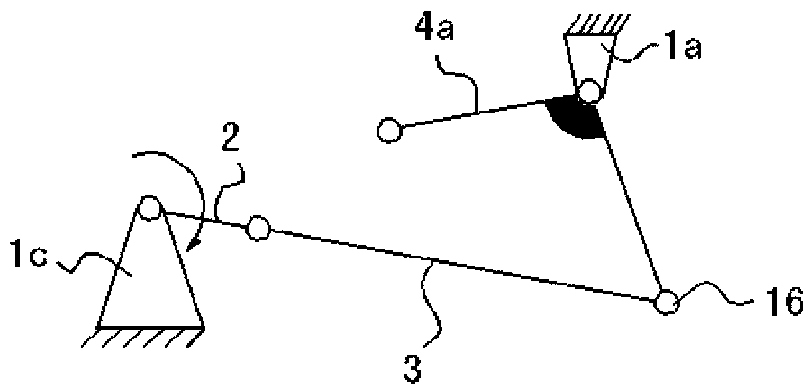
[0021] Such as figure 1 and image 3 As shown, the crank rocker mechanism set as the driving mechanism includes: one end of the connecting rod 3 is hinged with the crank 2 arranged on the crank frame 1c, and the other end of the connecting rod 3 is hinged with one end of the pull rod 7 to form a driving end hinge point 16;

[00...


PUM


Abstract

The invention discloses a vertical lifting device which is characterized by being provided with a parallelogrammic transmission mechanism, a crank rocker mechanism which serves as a driving mechanism, and a vertical lifting fork-shaped mechanism. The parallelogrammic transmission mechanism is characterized in that a first rocker and a second rocker are respectively hinged on top frames on both sides; the first rocker and the second rocker are connected by a tension rod; the outer side rod ends of the first rocker and the second rocker are respectively provided with a first slider and a second slider on the same height; and the first slider and the second slider are connected with a horizontal lifting framework through a sliding pair. According to the vertical lifting device, the horizontal and vertical lifting of a carried object is realized through the coupling motion of all the mechanisms, and the equipment has a simple structure and high controllability.

Description

technical field [0001] The invention relates to a vertical lifting device applied to conveying equipment of an automobile body-in-white welding line. Background technique [0002] With the rapid development of the automobile industry, the demand for welding conveyor lines with high tempo, high precision and high flexibility is getting stronger and stronger. Consumers are increasingly demanding on the quality of automobile bodies. Therefore, the welding line transmission equipment with strong automation ability, high stability and high transmission accuracy is more and more favored by various automobile manufacturers. At present, the reciprocating conveying equipment used by various automobile manufacturers is mostly realized in the way of cylinder push-pull, cylinder direct lifting, and cylinder balance. Due to the structure of the conveying equipment itself and the requirements of the conveying weight, the reciprocating conveying equipment powered by cylinders for lifting...

Claims


Application Information

Patent Timeline
Patent Type & Authority Applications(China)
IPC IPC(8): B66F7/06B66F7/08
Inventor 林巨广王健强王庆华杨献牛赵龙成子文汤东华王静
Owner ANHUI JEE AUTOMATION EQUIP CO LTD
Learn More