
Paper tube cutting machine

A cutting machine and paper tube technology, applied in metal processing, etc., can solve the problems of difficult fit and adaptation of fetal heart tubes, laborious withdrawal of short paper tubes, and low cutting efficiency, and achieve simple and practical structure, high cutting efficiency and good quality Effect

Active Publication Date: 2013-04-03
TIANJIN JINSHANYIDE PLASTIC PACKAGING CO LTD
View PDF7 Cites 25 Cited by
  • Summary
  • Abstract
  • Description
  • Claims
  • Application Information

AI Technical Summary

Problems solved by technology

[0004] The above self-made equipment has the following main problems: In order to avoid the deflection of the long paper tube on the fetal heart tube and affect the cutting quality, the disc cutter is set at the position corresponding to the upper part of the fetal heart tube, so the long paper tube must be cut every time. Only when the paper tube is removed from the fetal heart tube can the short paper tube that has been cut be withdrawn, and then the long paper tube is reinstalled on the fetal heart tube before cutting. Obviously, the low cutting efficiency is the main problem of the above self-made equipment.
In addition, the diameter of the fetal heart tube is difficult to match and adapt to the inner diameter of the long paper tube. The long paper tube often loses its rotation when it is cut under force. more effort to exit

Method used


Image

  • Paper tube cutting machine
  • Paper tube cutting machine

Examples


Embodiment Construction

[0014] Further illustrate the present invention below in conjunction with embodiment and accompanying drawing.

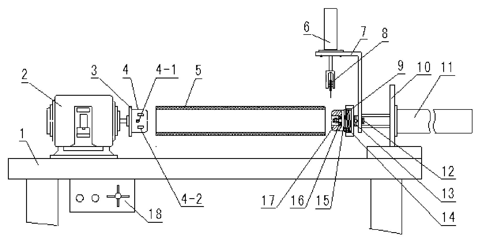
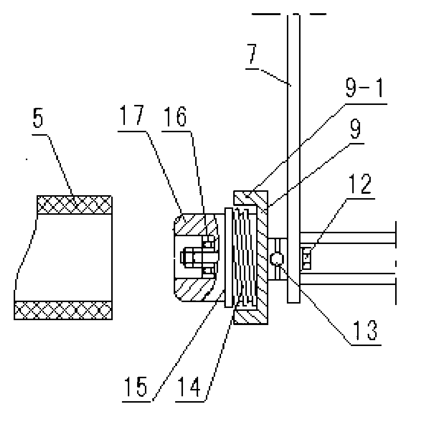
[0015] Such as figure 1 , 2 In the illustrated embodiment, the output shaft of the speed-regulating motor 2 at the left end of the machine table 1 of the paper tube cutting machine is provided with a first clamping disc 3, and the output shaft of the speed-regulating motor outside the clamping disc is provided with an air expansion The shaft 4, the inflation shaft includes an inflation nozzle 4-1 and a key bar 4-2. The seat plate 10 at the other end of the machine table 1 is fixed with a double-out rod cylinder 11, and the double-out rod is fixed with a cutting cylinder support 7. The cutting cylinder support is provided with a fixed shaft 12, and the fixed shaft 12 is rotatably supported by a second clamping disc. 9 and the support shaft 17, the support shaft is fixed to the second clamping disc, the second clamping disc 9 and the support shaft 17 are opposite an...


PUM


Abstract

The invention discloses a paper tube cutting machine. In the paper tube cutting machine, an output shaft of an adjustable-speed motor is provided with a first clamping disk and an expansion shaft; dual projection rods of a dual-projection-rod air cylinder are used for fixing a bracket of a cutting air cylinder; the bracket is provided with a fixed shaft; the fixed shaft is used for rotationally supporting a second clamping disk and a support shaft; the second clamping disk is provided with an edge boss which is jointed on a long paper tube; and the support shaft is sleeved with a long paper tube cut part ejection mechanism constructed by a spring and a push disk. The dual-protection-rod air cylinder can be used for realizing propulsion of the support shaft and the second clamping disk for tightening a long paper tube under the control of an electromagnetic valve control switch, and the edge boss of the second clamping disk is used for driving the spring to accumulate energy and driving the push disk to retract after being jointed with the long paper tube. The cutting air cylinder can be used for applying a pressure to a circular cutter under the control of the electromagnetic valve control switch, and the circular cutter returns back along with the cutting air cylinder after cutting is completed. The position of the cutting air cylinder on the bracket can be adjusted for changing the width of a short paper tube. The paper tube cutting machine has the outstanding advantages of simple and practical structure, high cutting efficiency and good quality.

Description

technical field [0001] The invention belongs to cutting mechanical equipment, in particular to a paper tube cutting machine. Background technique [0002] The film coil slitting machine is a device that simultaneously slits wide film coils into required widths. After slitting, each film with the required width is wound on a paper tube with the same width as the film at the same time. [0003] In the prior art, there is a self-made equipment for cutting long paper tubes into short paper tubes with the required width, including a motor and its deceleration mechanism, a rotating shaft connected to the decelerating mechanism, a fetal heart tube and a disc cutter set on the rotating shaft And the tool holder, the knife holder is provided with a pressurized handle. [0004] The above self-made equipment has the following main problems: In order to avoid the deflection of the long paper tube on the fetal heart tube and affect the cutting quality, the disc cutter is set at the posi...

Claims


Application Information

Patent Timeline
IPC IPC(8): B26D1/143B26D7/01B26D5/12B26D7/06
Inventor 王钢
Owner TIANJIN JINSHANYIDE PLASTIC PACKAGING CO LTD
Learn More