
Anti-scrape rolling guide groove

An anti-scratch and guide groove technology, applied in the direction of guiding/positioning/alignment devices, etc., can solve the problems of rapid wear of guide grooves, high material consumption, frequent replacement, etc., and achieve high stability of rolled pieces, remarkable effect, The effect of low production cost

Inactive Publication Date: 2013-04-03
JIANGSU YONGGANG GROUP CO LTD
View PDF6 Cites 6 Cited by
  • Summary
  • Abstract
  • Description
  • Claims
  • Application Information

AI Technical Summary

Problems solved by technology

[0002] The current guide groove is generally composed of a guide groove body and a guide groove cover. One or more guide grooves are arranged in sequence to form a channel. Friction, the friction between the rolled piece and the guide groove is very large, so the guide groove wears quickly, the replacement is frequent, and the material consumption is high

Method used


Image

  • Anti-scrape rolling guide groove
  • Anti-scrape rolling guide groove
  • Anti-scrape rolling guide groove

Examples


Embodiment Construction

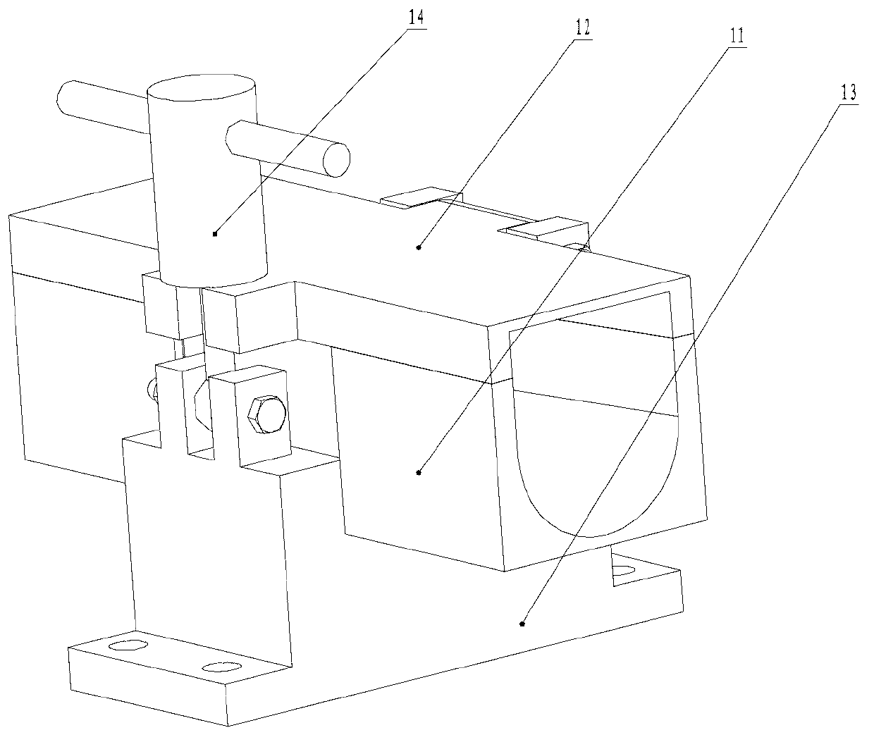
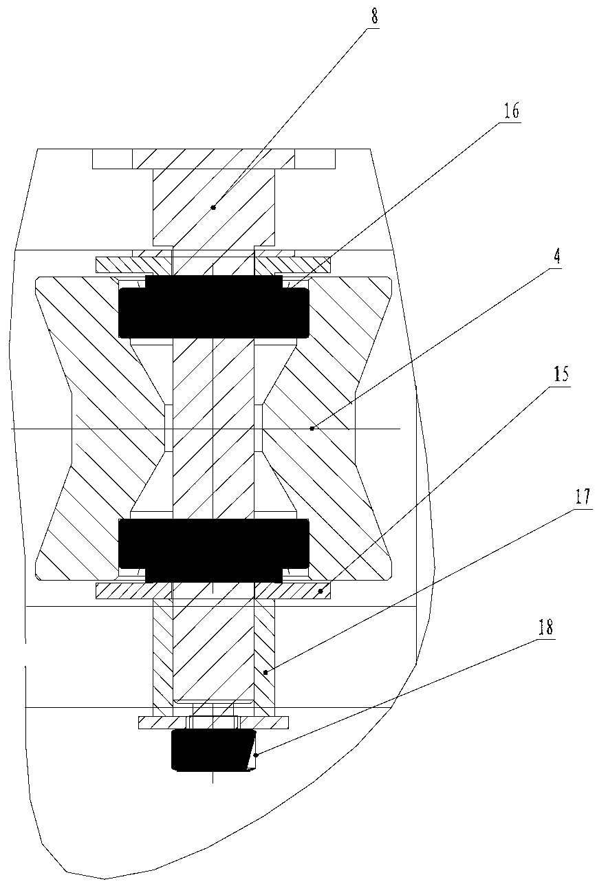
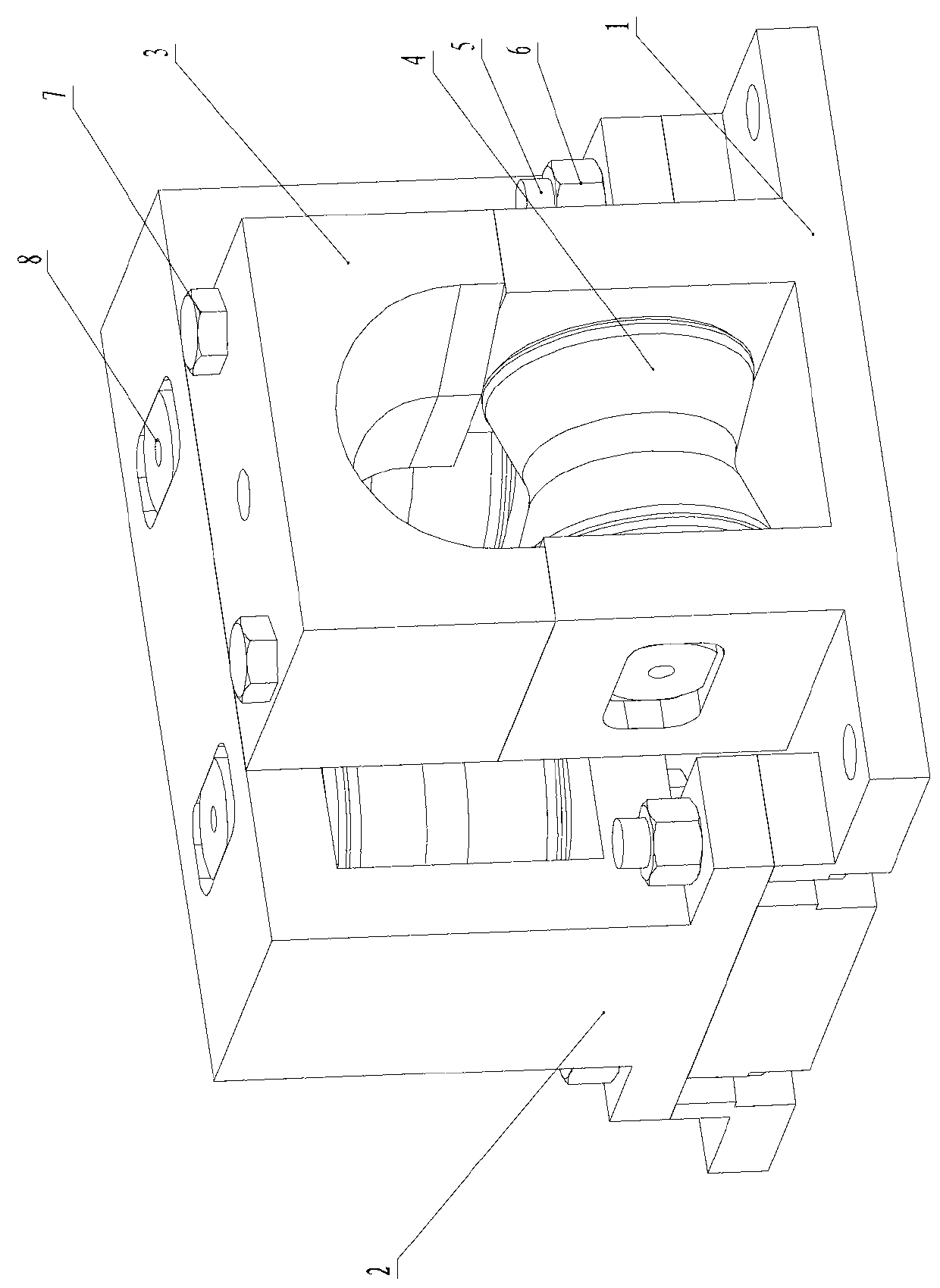
[0014] An anti-scratch rolling guide groove provided in this embodiment has a structure as shown in the figure, including a rolling element device 9 and a sliding guide groove 10 . Among them, the rolling body device includes a lower guide roller seat 1, which is equipped with a lower guide roller 4, and the rolled piece passes on the guide roller, and the guide roller can hold up the rolled piece; Left and right guide roller housing 2, left and right guide roller 5 and right guide roller 6 that are equated with lower guide roller size are respectively equipped with in this left and right guide roller housing, can prevent like this rolling piece side from being scratched. Then the left and right guide roller seats are fixed on the lower guide roller guide roller seats by connecting bolts and nuts. At the same time, a guide roller shaft 8 runs through the lower guide roller, wherein a bearing 16 is arranged symmetrically in the center of the outer side of the guide roller shaft...


PUM


Abstract

The invention relates to an anti-scrape rolling guide groove. The groove comprises a rolling body device and a slide guide groove, wherein the slide guide groove is formed in the side of the rolling body device; the rolling body device comprises a lower guide roller base; a lower guide roll is arranged in the lower guide roller base; a left guide roll base and a right guide roll base are arranged behind the lower guide roller base; and the left side and the right side of the left guide roll and the right guide roll are respectively provided with a left guide roll and a right guide roll. The guide groove is of a box body structure and is provided with a guide roll rolling body, when a rolling component passes through the interior of the guide groove, the guide rolls play a role of clamping the rolling component, and the rolling component is not easy to vibrate and is high in stability. The groove is suitable for rolling a high-added value linear product and can protect the surface of the rolling component, the phenomena of scraping steel and sticking steel are avoided, and the surface of the rolling component is not scraped. The anti-scrape rolling guide groove is obvious in effect, high in practicability, simple in structure, simple and convenient in operation and low in cost, and the operation efficiency is improved.

Description

technical field [0001] The invention relates to the technical field of steel rolling equipment, in particular to a guide groove device. Background technique [0002] The current guide groove is generally composed of a guide groove body and a guide groove cover. One or more guide grooves are arranged in sequence to form a channel. Friction, the friction between the rolled piece and the guide groove is very large, so the guide groove wears quickly, the replacement is frequent, and the material consumption is large. In order to reduce the wear of the guide groove, or in order to meet the production needs of high value-added products and reduce the scratches of the guide groove on the rolled piece, some guide grooves are designed in the form of wearing parts, such as the spray gun for rolling steel disclosed in Chinese Patent No. ZL200620071597. Water type rolling guide groove. At present, rolling steel types with high added value content, especially cold heading steel, has re...

Claims


Application Information

Patent Timeline
IPC IPC(8): B21B39/14
Inventor 汪建元
Owner JIANGSU YONGGANG GROUP CO LTD
Learn More