Eureka AIR delivers breakthrough ideas for toughest innovation challenges, trusted by R&D personnel around the world.

Cylinder part cleaning machine

A washing machine and parts technology, applied in the direction of dryers, conveyor objects, cleaning methods and appliances, etc., can solve problems such as high labor intensity, dead cleaning angles, inadequate cleaning, etc., and achieve the effect of improving cleaning efficiency

Active Publication Date: 2013-04-03
安徽宝辉清洗设备制造有限公司
View PDF7 Cites 45 Cited by
  • Summary
  • Abstract
  • Description
  • Claims
  • Application Information

AI Technical Summary

Problems solved by technology

In the prior art, the cleaning of oil cylinder parts is usually done manually. Manual cleaning is not only labor-intensive, but also low in efficiency, and the cleaning is not in place and the cleaning effect is poor.
In the prior art, special equipment is also used to clean the parts of the oil cylinder. The parts of the oil cylinder are transported to the cleaning room through the carrier table, and the parts of the oil cylinder are washed through the pipelines and nozzles in the cleaning room. Flush the road and the nozzle, because the bearing platform stops after reaching the fixed position, so this cleaning method cannot change the cleaning position of the cylinder parts, so the cleaning is not sufficient. In addition, for parts with an inner cavity, this kind of cleaning method cannot The cleaning method leaves a cleaning dead angle, and the cleaning is not in place

Method used


Image

  • Cylinder part cleaning machine
  • Cylinder part cleaning machine
  • Cylinder part cleaning machine

Examples


Embodiment Construction

[0034] The specific implementation manner of the present invention will be described below in conjunction with the accompanying drawings.

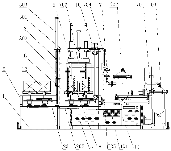
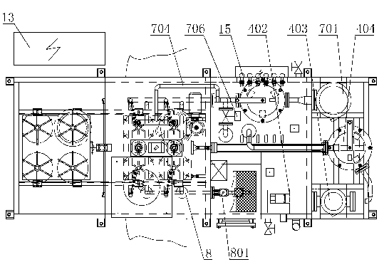
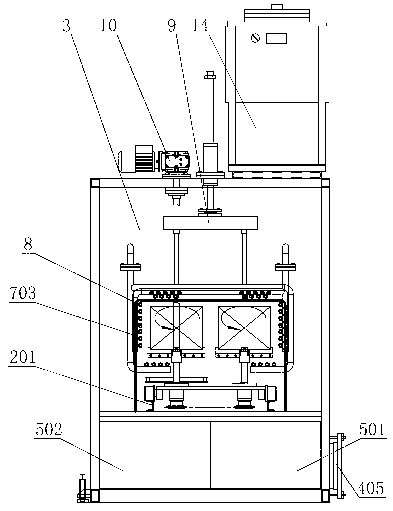
[0035] See figure 1 , figure 2 , image 3 , the present invention comprises frame 1 and electrical control cabinet 13, and horizontally on frame 1, workpiece station 2, cleaning room 3, water treatment system 4 are arranged in sequence; the bottom of cleaning room 3 is provided with water tank 5, and water tank 5 extends to water treatment System 4, water tank 5 includes sewage tank 501 and clean water tank 502, electric heating tube 15 is housed in clean water tank 502, track 201 is arranged on workpiece station 2, track 201 extends to cleaning room 3 and is fixedly connected with the inner wall of cleaning room 3, track The deflector 202 is arranged below the 201, and the deflector 202 extends out of the cleaning chamber 3, and is fixedly connected with the support plate 11 in the sewage tank 501; it also includes a transport vehicle ...


PUM


Abstract

The invention discloses a cylinder part cleaning machine, which comprises a frame and an electric control cabinet, wherein the frame is horizontally provided with a workpiece station, a cleaning chamber and a water treatment system; a water tank is arranged below the cleaning chamber, extends to the water treatment system and comprises a waste water tank and a clear water tank; an electric heating tube is arranged in the clear water tank; the workpiece station is provided with a track which extends to the cleaning chamber to be fixedly connected with the inner wall of the cleaning chamber; and a guide plate is arranged below the track. The cleaning machine further comprises a conveying vehicle assembled on the track, and a cleaning pipeline, a drying pipeline, a lifting probe cleaning device and a driving device which are arranged in the cleaning chamber, wherein the conveying vehicle is provided with a plurality of bearing disks which can rotate 360 degrees; and the cleaning pipeline is divided into two paths, one of which directly leads to the cleaning chamber to clean the outer surface of a cylinder part, and the other of which enters the probe cleaning device through a pipe to clean the inner chamber of the cylinder part. The cylinder part cleaning machine can clean the inner and outer surfaces of a plurality of cylinder parts and is low in labor intensity, high in cleaning efficiency and good in cleaning effect.

Description

technical field [0001] The invention relates to a cleaning device, in particular to a cleaning device for oil cylinder parts. Background technique [0002] The hydraulic cylinder is an energy conversion device that converts hydraulic energy into mechanical energy for reciprocating linear motion. It is basically composed of cylinder barrel and cylinder head, piston and piston rod, sealing device, buffer device and exhaust device. It is widely used. Its cylinder The cleanliness of the body is directly related to the stability and service life of the entire product. In the prior art, the cleaning of oil cylinder parts is usually done manually. Manual cleaning is not only labor-intensive, but also low in efficiency, and the cleaning is not in place and the cleaning effect is poor. In the prior art, special equipment is also used to clean the parts of the oil cylinder. The parts of the oil cylinder are transported to the cleaning room through the carrier table, and the parts of ...

Claims


Application Information

Patent Timeline
IPC IPC(8): B08B3/02B08B3/10C02F9/12B65G47/74F26B21/00
Inventor 施建红
Owner 安徽宝辉清洗设备制造有限公司
Why Eureka
Eureka Blog
Learn More