Chemical catalysis reactor

A technology of chemical catalysis and reactors, applied in the field of reactors, can solve the problems of widely varying reaction effects, achieve the effects of increasing residence reaction time, huge market prospects, and easy promotion and application

Inactive Publication Date: 2013-04-03
NANJING DELEI SCI & TECH
View PDF4 Cites 2 Cited by
  • Summary
  • Abstract
  • Description
  • Claims
  • Application Information

AI Technical Summary

Problems solved by technology

The existing design is often to set up a reaction tank, the reaction tank includes an inlet and an outlet, and there is a reaction layer in the reaction tank, but different reaction layers may have different reaction effects

Method used


Image

  • Chemical catalysis reactor
  • Chemical catalysis reactor
  • Chemical catalysis reactor

Examples


Embodiment

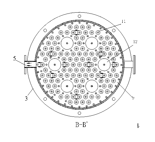
[0020] Such as Figure 1~Figure 5 As shown, this embodiment discloses a chemical catalytic reactor, comprising a reaction tank body 3, the lower end of the reaction tank body 3 is a material inlet, and the side wall of the reaction tank body 3 is provided with a material outlet 5; A first baffle plate 6 and a second baffle plate 7 are arranged upward, thereby dividing the inside of the reaction tank into a feed chamber 8 , a discharge chamber 9 and a reflux chamber 10 from bottom to top. A riser pipe 11 communicating with the feed chamber 8 and the return chamber 10 is provided between the first baffle plate 6 and the second baffle plate 7 . The second baffle 7 is provided with a return pipe 12 communicating with the return chamber and the discharge chamber. The material outlet 5 is located between the first baffle 6 and the second baffle 7 and communicates with the discharge chamber 9 . The feed chamber 8 is provided with a flow divider 1, including a trumpet-shaped housing...


PUM


Abstract

The invention discloses a chemical catalysis reactor, comprising a reaction tank body. A material inlet is arranged in the lower end of the reaction tank body; a material outlet is arranged in the lateral wall of the reaction tank body; a first flow baffle and a second flow baffle are arranged inside the reaction tank body from bottom to top, so that the inside of the reaction tank body is divided into a feeding cavity, a discharging cavity and a backflow cavity from bottom to top; an ascending pipe communicating the feeding cavity with the backflow cavity is arranged between the first flow baffle and the second flow baffle; a backflow pipe communicating the backflow cavity with the discharging cavity is arranged on the second flow baffle; and a material outlet is located between the first flow baffle and the second flow baffle and is communicated with the discharging cavity. The chemical catalysis reactor provided by the invention is in an integrated structure, has small occupied area, and is convenient to popularize and apply. During the catalysis reaction, catalyst can be directly output through the material inlet, or the catalyst can be attached to the inside of the metal reaction tank body, through a plurality of tests, the chemical catalysis reactor provided by the invention has the advantages of simple structure, large market prospect and wide application range.

Description

technical field [0001] The invention relates to a reactor, especially a chemical catalytic reactor. Background technique [0002] Chemical catalytic reactors are common equipment in the chemical field, and are generally used for reactions of gases, liquids, solid powders and catalysts. The existing design is often to set a reaction tank, the reaction tank includes an inlet and an outlet, and a reaction layer is arranged in the reaction tank, but different reaction layers may have different reaction effects. How to design a reactor to improve gas and liquid catalytic reactions is a common technical problem and technical difficulty in this field. Contents of the invention [0003] Purpose of the invention: The technical problem to be solved by the present invention is to provide a chemical catalytic reactor for the deficiencies of the prior art. [0004] In order to solve the above technical problems, the present invention discloses a chemical catalytic reactor, which incl...

Claims


Application Information

Patent Timeline
IPC IPC(8): B01J8/08
Inventor 吴浩
Owner NANJING DELEI SCI & TECH
Why Eureka
Try Eureka