
Automatic feeding and aerating device for pound

A technology of an oxygenation device and fish pond, which is applied in transmission devices, gear transmission devices, fish farming, etc., can solve the problems of large rotation space, impaired oxygenation efficiency, and inability to achieve, and achieves the effect of increasing the amount of dissolved oxygen.

Inactive Publication Date: 2013-04-03
朱铁峰
View PDF8 Cites 13 Cited by
  • Summary
  • Abstract
  • Description
  • Claims
  • Application Information

AI Technical Summary

Problems solved by technology

But above-mentioned patent scheme still has the following deficiencies: 1, utilize the reaction moment produced respectively at the end of two transmission arms when two impellers rotate on their own to drive two impellers to revolve around the center of two transmission arms, but when the rotating speed of two impellers is slower or When the two transmission arms are relatively short, the reaction moment generated is relatively small, and the revolution is difficult to realize, especially when there are floating aquatic plants in the fish pond, the revolution is even more difficult to realize, or even impossible; 2. Use the reverse rotation of the motor to stop the revolution, and the impeller can only use straight blades, so the upper and lower water in the fish pond cannot flow and exchange, and the oxygenation efficiency is obviously damaged; 3. Only oxygenation can be achieved, in order to realize fish feeding It is still necessary to arrange a fixed feeding machine in the fish pond, because the 360-degree mobile feeding machine needs a large rotation space, and there is mutual interference between the two

Method used


Image

  • Automatic feeding and aerating device for pound
  • Automatic feeding and aerating device for pound
  • Automatic feeding and aerating device for pound

Examples


Embodiment Construction

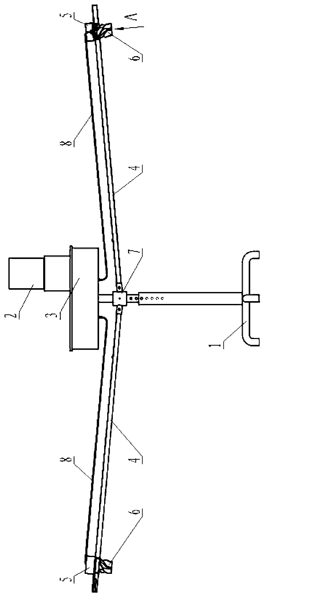
[0018] see figure 1 , the whole aeration device is mainly composed of support base 1, motor 2, planetary gearbox 3, rotary arm 4, feeding device 5, spiral impeller 6, rotary arm joint 7 and flexible shaft 8.

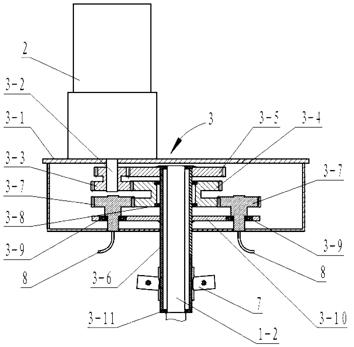
[0019] Such as figure 2 As shown, the planetary gearbox 3 is composed of a casing 3-1, an input shaft 3-2, a driving duplex gear 3-3, a central duplex gear 3-4, a revolution transmission gear 3-5, and a hollow central shaft 3 -6 and two planetary gears 3-7, wherein the hollow central shaft 3-6 is pierced and fixed on the lower side plate of the box body 3-1, and the revolution transmission gear 3-5 is fixed on the hollow central shaft 3-6 Stretching into the top of the box body 3-1, the central duplex gear 3-4 is located on the lower side of the revolving transmission gear 3-5 and is supported on the hollow central shaft 3-6 by two first bearings 3-8; the active duplex gear The gear 3-3 is fixed on the input shaft 3-2, and the upper one meshes with the revolving tran...


PUM


Abstract

The invention relates to cultivation of fish, in particular to an automatic feeding and aerating device for a pound. The device comprises a supporting seat, an electric motor, an epicyclic gearbox, revolving arms fixed with the epicyclic gearbox together and extended towards both sides and impeller wheels respectively arranged at the remote ends of the revolving arms, and is characterized in that the epicyclic gearbox divides the rotation of the electric motor into two paths of output, wherein one path of output drives the revolving arms so as to realize that the impeller wheels revolve around a center rod, and the other path of output drives the impeller wheels to rotate axially through a flexible shaft so as to realize aerating. In the aerating device, the revolution of the impeller wheels does not depend on the axial rotation of the impeller wheels; and therefore, the impeller wheels can be screw impeller wheels, so that the rotation direction of the impeller wheels is changed, water on the surface of the pound can be conveyed underwater, and water at the lower part of the pound can be conveyed towards the surface so as to increase the dissolved oxygen in the pound.

Description

technical field [0001] The invention relates to fish cultivation, in particular to a fish feeding and aeration device. Background technique [0002] The level of dissolved oxygen in the pond has a direct impact on the growth and survival of fish. Under high dissolved oxygen, fish eat vigorously, have high digestion, fast growth, high feed efficiency, and fast oxidation of organic matter, which can promote material Circulates and eliminates some toxic biological metabolites. Oxygenation in fish ponds is an important aquaculture method in the field of aquaculture to ensure the safe growth of fish, shrimp and other aquatic products, prevent weed damage, and increase production. At present, there are various types of aerators used by aquaculture enterprises, such as waterwheel type, spray type, biological rotary drum aerator, and blast gas transmission. [0003] The utility model patent with the authorized notification number CN86206535U discloses "an impeller type aerator for...

Claims


Application Information

Patent Timeline
IPC IPC(8): A01K63/04A01K61/02F16H1/28
Inventor 江帆黄春曼
Owner 朱铁峰
Learn More