
Loudspeaker structure

A loudspeaker and consistent technology, applied in the mechanical field, can solve the problem that the height of the loudspeaker cannot be reduced, and achieve the effect of simplifying the processing cost

Inactive Publication Date: 2013-03-27
东星电声科技(东莞)有限公司
View PDF2 Cites 1 Cited by
  • Summary
  • Abstract
  • Description
  • Claims
  • Application Information

AI Technical Summary

Problems solved by technology

[0003] The invention proposes a loudspeaker structure, which solves the problem in the prior art that the loudspeaker structure is greatly affected by the voice coil and the height of the loudspeaker cannot be lowered

Method used


Image

  • Loudspeaker structure
  • Loudspeaker structure
  • Loudspeaker structure

Examples


Embodiment Construction

[0030] The following will clearly and completely describe the technical solutions in the embodiments of the present invention with reference to the accompanying drawings in the embodiments of the present invention. Obviously, the described embodiments are only some, not all, embodiments of the present invention. Based on the embodiments of the present invention, all other embodiments obtained by persons of ordinary skill in the art without creative efforts fall within the protection scope of the present invention.

[0031] Such as Figure 6-Figure 11 As shown, the loudspeaker structure of the present invention includes: washer 4, a first magnet 31, a T-shaped iron 2 and two voice coils 8, the first magnet 31 is arranged in the middle of the washer 4, and communication channels are arranged at both ends. hole; the shape of the T-shaped iron 2 is consistent with the washer 4, and both ends are raised, and the raised parts are respectively set in the through holes at the two ends...


PUM


Abstract

The invention provides a loudspeaker structure which comprises a washer, a first magnet, T-shaped iron and at least two voice coils, wherein the first magnet is arranged in the middle of the washer, and through holes are arranged at two ends; the shape of the T-shaped iron is identical to that of the washer, two ends of the T-shaped iron are protruded, the protruding parts are respectively sleeved in the through holes at two ends of the washer; and the first magnet is clamped between the washer and the T-shaped iron, and the voice coils are respectively sleeved on the protrusions of the washer. The magnet and the voice coils are not on the same axial line, but the T-shaped iron contacted with the magnet and the washer transmit magnetic induction linesto magnetic gaps to provide energy for vibration of the voice coils; the height space of the loudspeaker can be utilized to the largest extent, horns and voice boxes can be thinner and minimized, simultaneously the shape of the magnet does not need to be corresponding to or similar to that of the voice coils, and processing cost is simplified.

Description

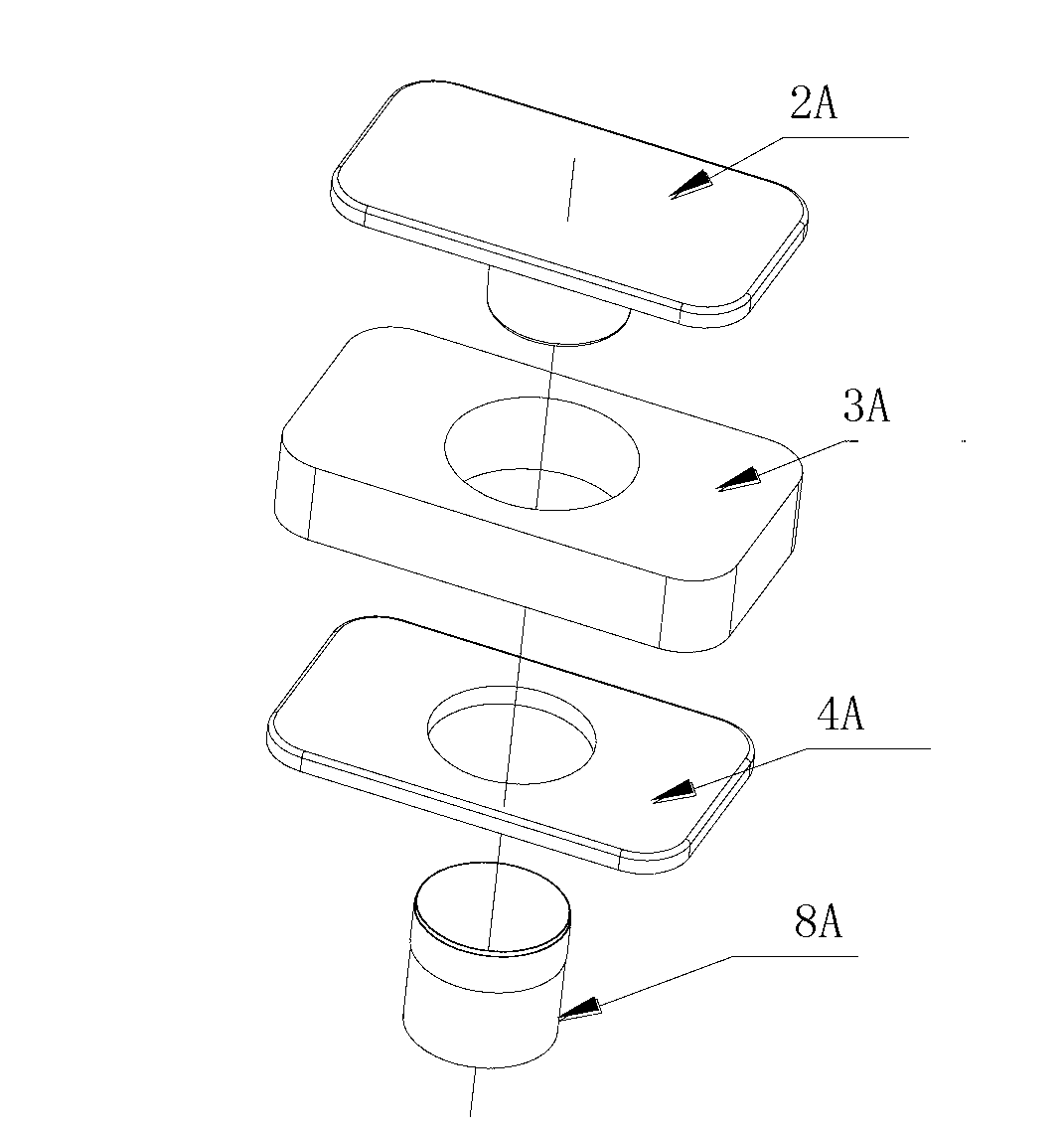
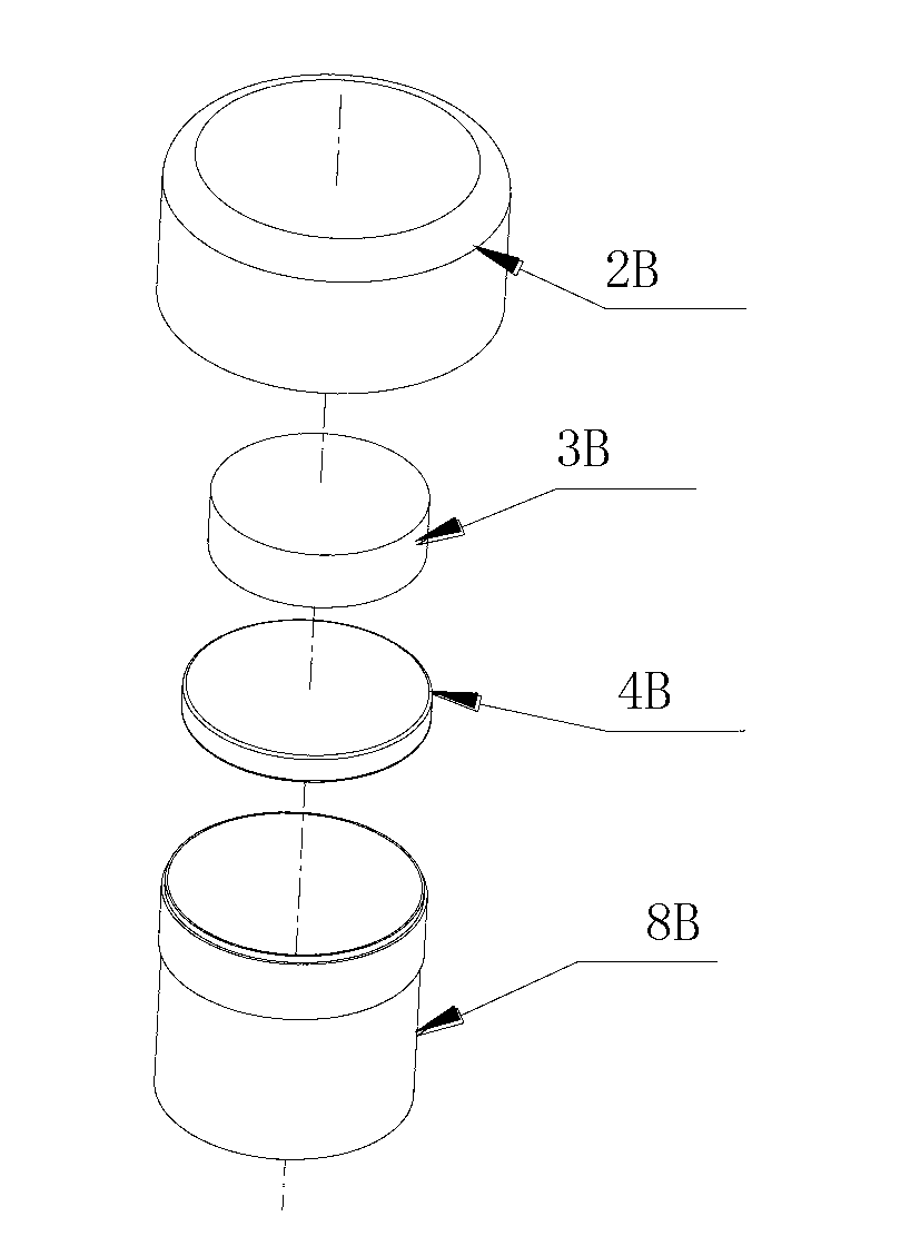
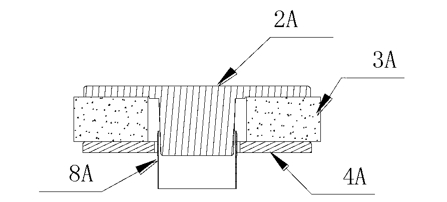
technical field [0001] The invention relates to the mechanical field, in particular to a loudspeaker structure. Background technique [0002] The magnetic circuit structure used in traditional loudspeakers is usually that the voice coil and the magnetic circuit are on the same axis, such as Figure 1-Figure 5 As shown, the labels are T-shaped iron 2A, 2B, magnet 3A, 3B, 3C, washer 4A, 4B, voice coil 8A, 8B, 8C, the magnets are symmetrically distributed along the axis of the voice coil, and the magnets are usually inside the voice coil called internal magnetism (see figure 2 and Figure 4 ), outside the voice coil is called the external magnet (see figure 1 and image 3 ). The shape of the voice coil is similar to the shape of the magnet. If the voice coil is circular, the magnet is usually also circular; since the magnet part is in the axial direction of the voice coil and at the bottom of the voice coil (such as image 3 , Figure 4 and Figure 5 As shown), the str...

Claims


Application Information

Patent Timeline
IPC IPC(8): H04R9/06H04R9/02
Inventor 冯维伦潘建平
Owner 东星电声科技(东莞)有限公司
Learn More