Multi-slot lighting device

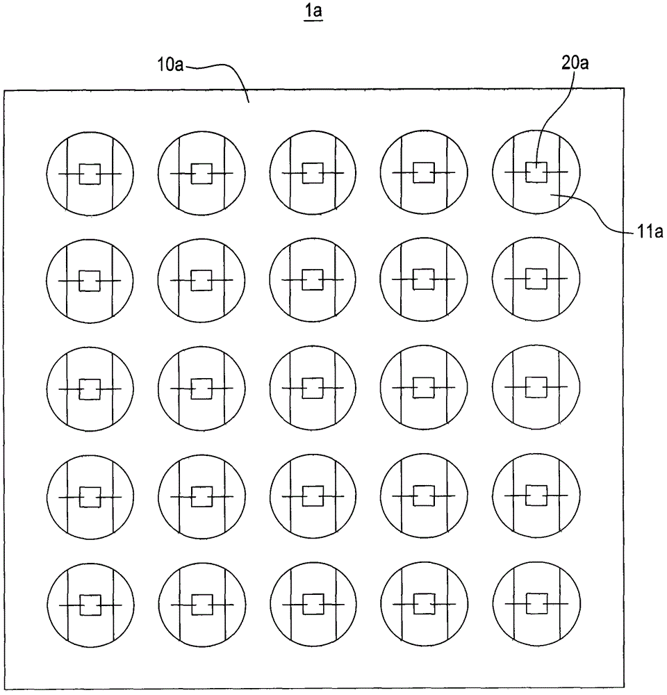
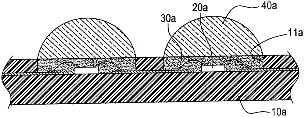
A light-emitting device and slot-type technology, applied in the direction of semiconductor devices, electrical components, circuits, etc., can solve the problems of affecting the strength of the substrate 10a, increasing the assembly time and cost, and breaking the substrate 10a, thereby increasing practicability and reducing assembly. Working hours and time, the effect of reducing the overall cost

Active Publication Date: 2016-02-17
EPISTAR CORP
View PDF4 Cites 0 Cited by
  • Summary
  • Abstract
  • Description
  • Claims
  • Application Information

AI Technical Summary

Problems solved by technology

[0004] In the above structure, since the lenses 40a need to be combined on the LED chip 20a respectively, the overall assembly time and cost are increased. In addition, the number of the grooves 11a is large and dense, thus requiring a larger substrate area. Affect the strength of the substrate 10a, easily cause the substrate 10a to crack, thereby reducing the product yield

Method used


Image

  • Multi-slot lighting device
  • Multi-slot lighting device
  • Multi-slot lighting device

Examples


Embodiment Construction

[0034] The detailed description and technical content of the present invention are described below with accompanying drawings. However, the attached drawings are provided for reference and illustration only, and are not intended to limit the present invention.

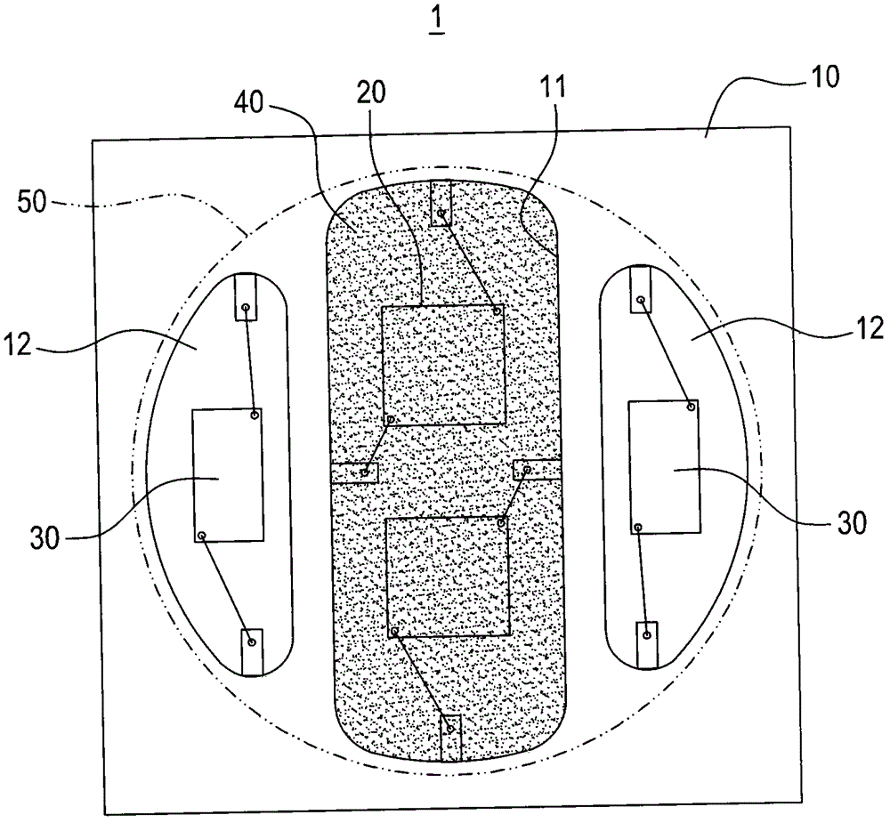
[0035] Please refer to image 3 and Figure 4 , are respectively a schematic plan view and a cross-sectional view of the multi-slot light emitting device of the present invention; the multi-slot light emitting device 1 of the present invention includes a base 10, a first light emitting unit 20, at least two second light emitting units 30, a light conversion Layer 40, and a lens 50.

[0036] The base 10 has a central groove 11 and at least two side grooves 12 symmetrically disposed outside the central groove 11 . The base 10 can be configured as a ceramic base, and has a plurality of conductive vias 13 and an inner circuit 14 , which is not limited in actual implementation.

[0037] In this embodiment, the first ligh...


PUM


Abstract

The invention discloses a multi-groove light emitting device, which comprises a base, a blue light emitting unit, at least two red light emitting units, a light conversion layer and a lens. The base has a central groove and at least two symmetrically arranged outside the central groove. The side groove, the blue light-emitting unit is set in the central groove, the two red light-emitting units are respectively arranged in the two side grooves, the light conversion layer covers the blue light-emitting unit, the lens is convexly set on the base, and sealed A central groove and at least two side grooves; thereby increasing the light extraction efficiency of the LED chip, improving product yield, and reducing overall assembly time and cost.

Description

technical field [0001] The invention relates to a light emitting device, in particular to a multi-slot light emitting device capable of emitting warm white light. Background technique [0002] Light Emitting Diodes (Light Emitting Diode, LED) have gradually replaced traditional tungsten lamps, fluorescent lamps or mercury lamps and are widely used in various lamps due to their advantages such as low energy consumption, power saving, long service life, small size, and fast response. . [0003] Please refer to figure 1 and figure 2 As shown, they are respectively a schematic plan view and a partial cross-sectional view of an existing LED light-emitting module; the LED light-emitting module 1a includes a substrate 10a, a plurality of LED chips 20a (such as blue LED chips 20a), fluorescent glue 30a such as (yellow fluorescent glue 30a) And a plurality of lenses 40a, the substrate 10a is provided with a plurality of grooves 11a arranged in an array, the LED chips 20a are resp...

Claims


Application Information

Patent Timeline
Patent Type & Authority Patents(China)
IPC IPC(8): H01L25/13H01L33/50H01L33/58
CPCH01L2224/48091H01L2224/48137H01L2924/00014
Inventor 周锡烟郑子淇
Owner EPISTAR CORP
Why Eureka
Try Eureka