
Crack width adjusting device

A technology of width adjustment and slits, applied in installation, lasers, instruments, etc., can solve the problems of difficulty in precise control and consume a long time, and achieve the effect of improving the forming time, precision and efficiency.

Active Publication Date: 2013-03-27
CHARM ENG CO LTD
View PDF6 Cites 1 Cited by
  • Summary
  • Abstract
  • Description
  • Claims
  • Application Information

AI Technical Summary

Problems solved by technology

[0007] However, it is difficult to precisely control the gap width adjustment device in the past because both the X-axis blade and the Y-axis blade can only move to the center or the outside.
That is, the gap width adjustment device cannot move the two X-axis blades and Y-axis blades independently, but will move to the center or the outer edge in conjunction, so it takes a long time to move it to the position of the defective pixel. time

Method used


Image

  • Crack width adjusting device
  • Crack width adjusting device
  • Crack width adjusting device

Examples


Embodiment Construction

[0035] Embodiments according to the present invention will be described below with reference to the drawings. However, the present invention is not limited to the embodiments disclosed below, and various forms different from each other can be realized. This embodiment is provided only for the purpose of disclosing the present invention and fully informing those skilled in the art about the scope of the present invention. .

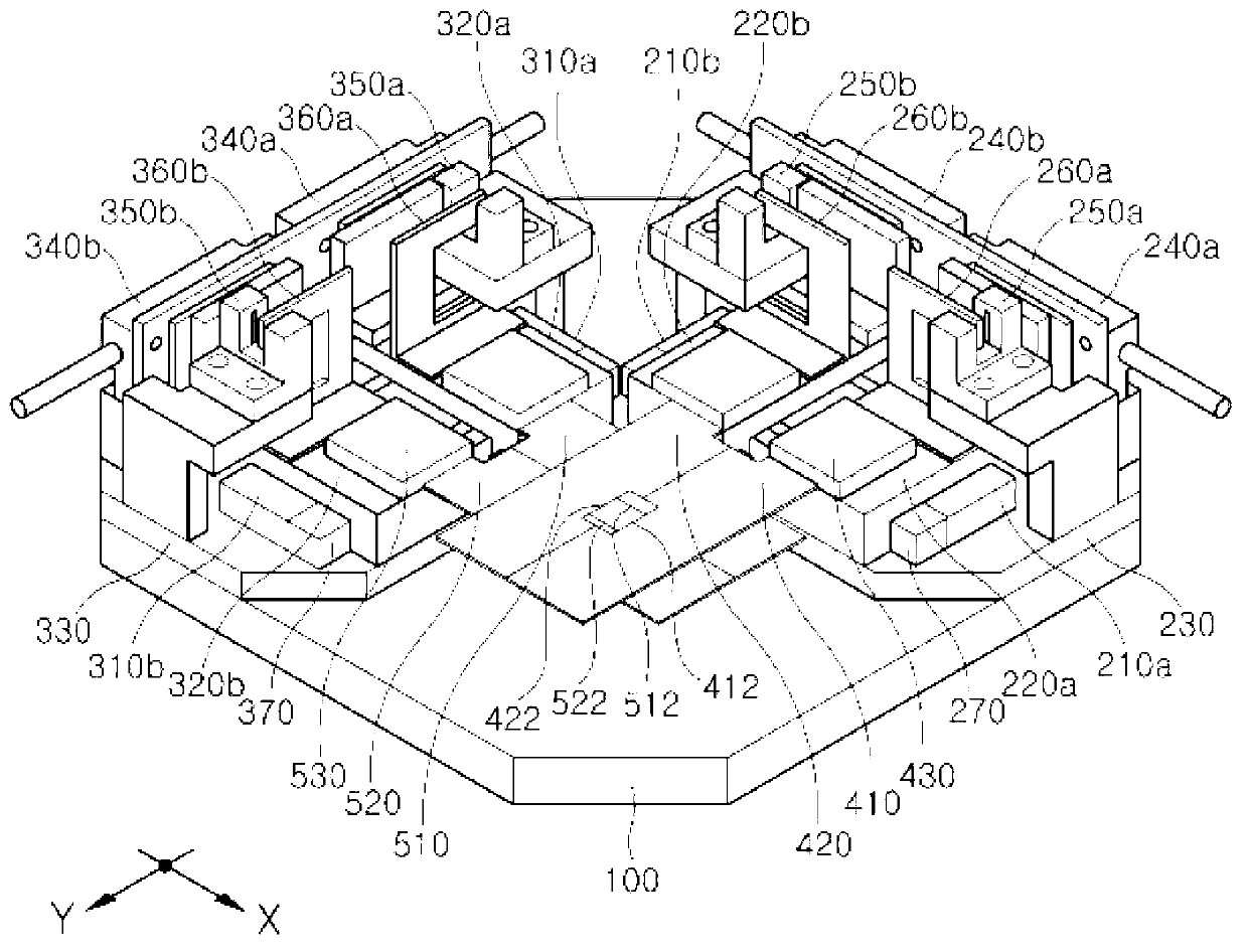
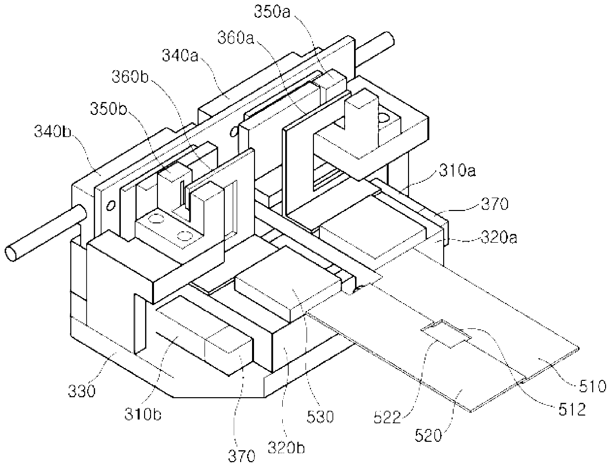
[0036] figure 1 It is an oblique view of a gap width adjusting device according to an embodiment of the present invention, figure 2 As a side oblique view, the main components of the gap width adjusting device will be mainly described below.

[0037] refer to figure 1 and figure 2 , according to the embodiment of the present invention, the gap width adjusting device includes: a platform 100; for example, a first linear motor 200, which is arranged on the X-axis edge of the platform 100; for example, a second linear motor 300, which is arranged on the...


PUM


Abstract

The invention discloses a crack width adjusting device comprising first, second, third and fourth movable terminals, and first and second stators, wherein the first and second movable terminals are connected to mutually parallel first and second crack blades respectively, and the third and fourth movable terminals are connected to third and fourth crack blades respectively. The third and fourth crack blades are orthogonal to the first and second crack blades and are mutually parallel to each other. The first stator is arranged at the lower parts of the first and second mutually parallels and is used for driving the first and second movable terminals to move linearly respectively. The second stator is arranged at the lower parts of the third and fourth mutually parallels and is used for driving the third and fourth movable terminals to move linearly respectively.

Description

technical field [0001] The present invention relates to a gap width adjustment device, in particular to a gap width adjustment device for repairing defective pixels of a flat panel display device such as a liquid crystal display device (LCD). Background technique [0002] Development of flat panel display devices such as organic light emitting diode display (OLED), plasma display panel (PDP), liquid crystal display (LCD), etc., replacing cathode ray tubes (cathode ray tubes) tube; CRT), is actively in progress. [0003] Among them, the most widely used liquid crystal display device includes gate lines, data lines, a first substrate on which thin film transistors and pixel electrodes are formed, a second substrate on which color filters, black matrixes, common electrodes, etc. are formed, and The liquid crystal layer is arranged between the first and second substrates. This liquid crystal display device turns the liquid crystal containing the liquid crystal layer to change ...

Claims


Application Information

Patent Timeline
Patent Type & Authority Applications(China)
IPC IPC(8): G02B7/00G02F1/13
CPCH01S3/10069H02K1/17G02F1/1309G09G3/2003
Inventor 元龙渊池泳洙
Owner CHARM ENG CO LTD
Learn More