Gas stove

A gas stove and gas stove technology, applied in the field of gas stoves, can solve the problems of strong pressure, explosion, burning out of cooking pots and the like

Inactive Publication Date: 2013-03-27
陆光华
View PDF7 Cites 1 Cited by
  • Summary
  • Abstract
  • Description
  • Claims
  • Application Information

AI Technical Summary

Problems solved by technology

However, when people use these gas stoves, they occasionally do other things and often forget to turn off the gas. As a result, the food is burnt and the cooking pot is burnt; If the pressure in the pot is too high for a long time, it will not only burn the head of the pot, but also may cause an explosion. The consequences are unimaginable

Method used


Image

  • Gas stove
  • Gas stove
  • Gas stove

Examples


Embodiment Construction

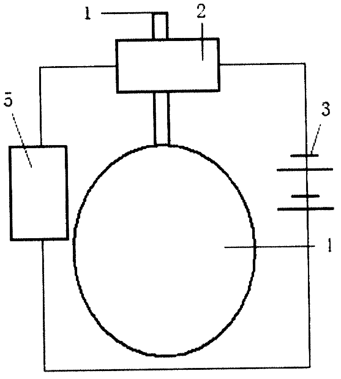
[0015] Described a kind of gas cooker, such as figure 1 As shown, it includes a gas pipe, a gas stove, a solenoid valve, a timer and a battery box; one end of the solenoid valve is connected to the gas tank, and the other end is connected to the gas stove; one end of the battery box is connected to the solenoid valve, and the other end is connected to the timer. The controller and the solenoid valve are connected by wires.

[0016] Preferably, the solenoid valve is a two-way valve, and its operating voltage is 3V, which is selected according to the battery box.

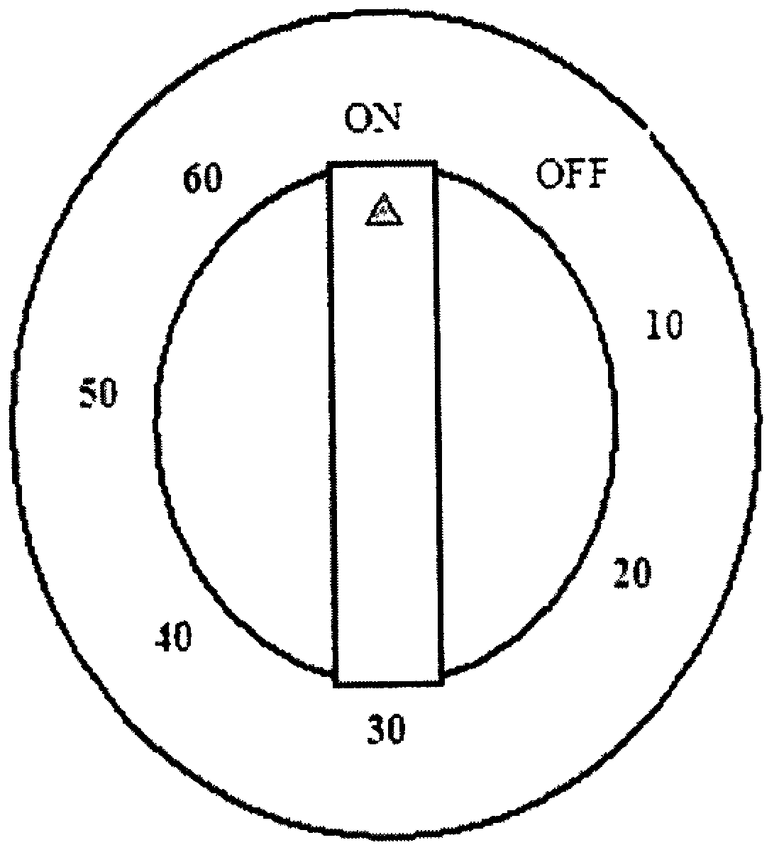
[0017] Such as image 3 As shown, the timer is adjustable from 0 to 60 minutes, and can be set to keep on if it exceeds 60 minutes.

[0018] Preferably, the output voltage of the battery box is 3V, which is the same as the operating voltage of the solenoid valve.

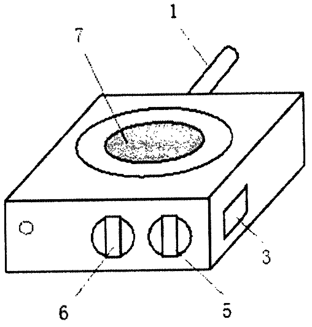
[0019] Such as figure 2 As shown, the timer is located on the side where the gas switch of the gas stove is located.

[0020] Using this invention to...


PUM


Abstract

The invention discloses a gas stove comprising a gas pipe, a gas oven, an electromagnetic valve, a timer and a battery case. A gas hole in one end of the electromagnetic valve is connected with a gas tank, and a gas hole in the other end of the electromagnetic valve is connected with the gas oven; one end of the battery case is connected with the electromagnetic valve, and the other end of the battery case is connected with the timer; and the timer is connected with the electromagnetic valve through a lead.

Description

Technical field: [0001] The invention relates to a gas stove, and mainly relates to a use time control system of the gas stove. Background technique: [0002] At present, there are many kinds of gas stoves sold in stores, which bring great convenience to people's lives. However, when people use these gas stoves, they occasionally do other things, often forget to turn off the gas, and as a result, the food is burnt and the cooking pot is burnt; If the pressure in the pot is too high for a long time, it will not only burn the head of the pot, but also may cause an explosion. The consequences are unimaginable. Invention content: [0003] According to the disadvantages of the traditional gas stove, we have provided a gas stove, which is equipped with a timing system, so that the conduction time of the gas pipe can be adjusted, so that the heating time can be adjusted, and the gas can be used when the user goes out. safety. [0004] Technical scheme of the present invention ...

Claims


Application Information

Patent Timeline
IPC IPC(8): F24C3/12
Inventor 陆光华
Owner 陆光华
Why Eureka
Try Eureka