
Wort kettle automatic cycle device comprising conical spiral coil and conical cover

An automatic circulation, conical technology, applied in the direction of beer brewing, wort preparation, biochemical equipment and methods, etc., can solve the problems of uneven mixing, low boiling intensity, large space occupation, etc., to achieve uniform boiling cycle, The effect of high boiling strength and easy preparation

Inactive Publication Date: 2013-12-11
曹玉升
View PDF4 Cites 0 Cited by
  • Summary
  • Abstract
  • Description
  • Claims
  • Application Information

AI Technical Summary

Problems solved by technology

[0002] At present, the wort boiling pot makes the wort boiling cycle in the following ways: the tube heater in the pot circulates the wort to flow between the tubes, there is a dead angle that does not flow, the mixing is uneven, and the boiling intensity is low; the power pump outside the pot circulates, which is the heater. It is located outside the pot, and the wort is pumped out from the boiling pot, heated by the heater outside the pot, and then flows back into the wort boiling pot. This form of wort circulation is strong, causing large mechanical damage, large heat loss, energy consumption, and occupancy. Large space and high investment cost; W-type pot bottom boiling circulation, simple structure and low cost, but this form of wort boiling circulation, divided into two areas, also has dead angles that do not circulate, uneven mixing, and low boiling intensity

Method used


Image

  • Wort kettle automatic cycle device comprising conical spiral coil and conical cover

Examples


Embodiment Construction

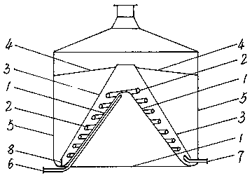
[0010] The invention is attached figure 1 As shown, the device is composed of a conical pot bottom 1, a conical spiral coil 2, a conical cover 3, and an umbrella-shaped liquid leakage tray 4, and the bottom of the cylindrical wort boiling pot 5 is set as a conical pot bottom 1 , Along the conical helical coil 2 on the conical pot bottom 1, the conical cover 3 is covered on the conical helical coil 2, and the umbrella-shaped liquid leakage disc 4 is covered on the conical cover 3. In order to prevent the condensed water from clogging the conical helical coil 2 and ensure the efficient operation of the device, the conical helical coil 2 is set so that one end enters the steam and the other end discharges the condensed water. Extend to the top of the conical pot bottom 1 and enter the pot 5. On the conical pot bottom 1, coil the pipe from top to bottom along the conical spiral, turn the disc to an end 7 of draining condensed water. In order to make the wort circulate well during...


PUM


Abstract

A wort kettle automatic cycle device comprises a conical pot bottom, a conical spiral coil, a conical cover and an umbrella-shaped leakage dish. The pot bottom of the cylindrical wort kettle is designed into a cone shape, a pipe coils on the conical pot bottom along the conical spiral, the conical cover covers on the conical spiral coil, and the umbrella-shaped leakage dish covers on the conical cover. The wort kettle automatic cycle device comprising the conical spiral coil and the conical cover has the advantages of being simple in structure, being convenient to implement, saving the energy, being environment friendly, being capable of achieving the automatic cycle in the wort boiling process with the power no required, providing no dead corner and serving as an ideal wort boiling device.

Description

technical field [0001] The invention relates to an automatic circulation device for a wort boiling pot composed of a conical spiral coil tube and a conical cover for beer production. Background technique [0002] At present, the wort boiling pot makes the wort boiling cycle in the following ways: the tube heater in the pot circulates the wort to flow between the tubes, there is a dead angle that does not flow, the mixing is uneven, and the boiling intensity is low; the power pump outside the pot circulates, which is the heater. It is located outside the pot, and the wort is pumped out from the boiling pot, heated by the heater outside the pot, and then flows back into the wort boiling pot. This form of wort circulation is strong, causing large mechanical damage, large heat loss, energy consumption, and occupancy. Large space and high investment cost; W-type pot bottom boiling circulation, simple structure and low cost, but this form of wort boiling circulation, divided into ...

Claims


Application Information

Patent Timeline
Patent Type & Authority Patents(China)
IPC IPC(8): C12C7/22
Inventor 徐亚军胡序建刘娟孙永涛刘玲赵慧丽宁玉门杨铭常艳华高杰曹玉升
Owner 曹玉升
Learn More