Robot having workpiece mass measurement function
A mass measurement and robotics technology, applied in the field of robotics, can solve the problem of large cycle times of robots, and achieve the effects of cost suppression and simple structure
- Summary
- Abstract
- Description
- Claims
- Application Information
AI Technical Summary
Problems solved by technology
Method used
Image
Examples
Embodiment 1
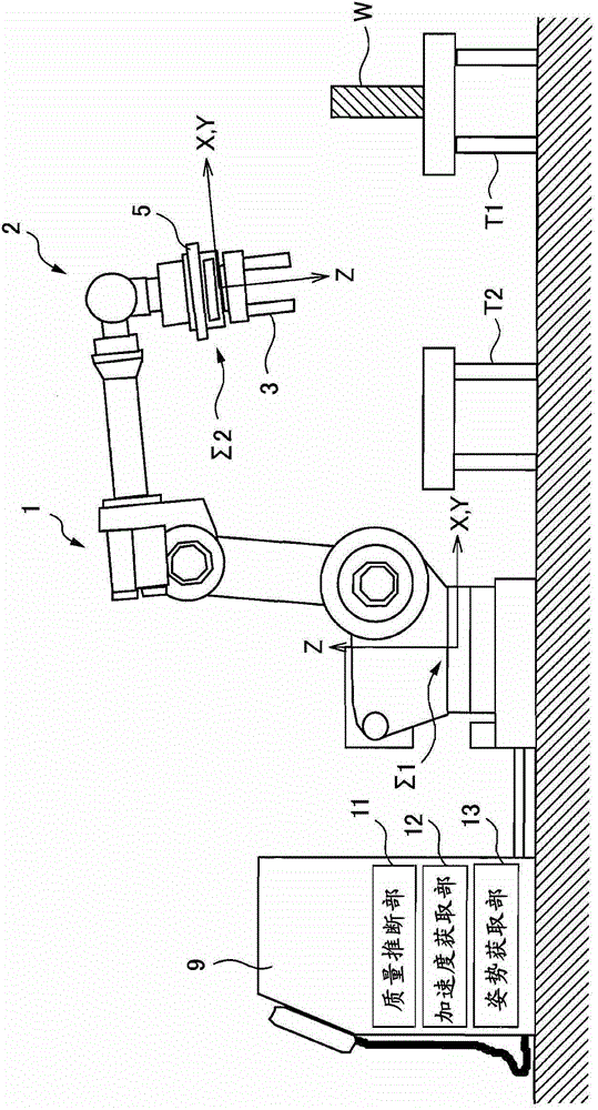
[0059] In the first embodiment, the mass of the hand 3 is known by other measurements. In addition, since a force sensor having three or more axes is used as the force sensor 5 , the force sensor 5 can detect a force of three parallel components.
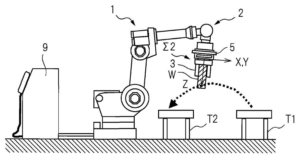
[0060] exist Figure 2B In , the workpiece W is held by the hand 3 of the robot 1, and the robot 1 and the workpiece W operate without contacting peripheral equipment or the like. At this time, if Figure 2B As shown, the output of the force sensor 5 when the robot 1 is operated so that the posture of the wrist of the robot 1 does not change is expressed by the following equation (1). In addition, the reason why the wrist is not changed is to reduce the influence of disturbances such as vibration of the robot.
[0061] F=(Mh+Mw)·R·{g+d 2 x / dt 2 +C(x, dx / dt)} (1)
[0062] Wherein, F is the force vector (detection value) detected by the force sensor 5,
[0063] Mh is the mass of hand 3,
[0064] Mw is the mass of workpiece W, ...
Embodiment 2
[0077] image 3 It is a figure which shows the operation|movement of the robot which concerns on Example 2 of this invention. It can be seen from the figure that the second embodiment is different from the first embodiment in that the acceleration sensor 6 is installed on the base of the hand 3 . In addition, also in the second embodiment, a force sensor with three or more axes is used as the force sensor 5 , so the force sensor 5 can detect a force of three parallel components. In the above-mentioned first embodiment, the vector {g+d is obtained by calculation 2 x / dt 2 +C(x, dx / dt)}, however, in the second embodiment, the above-mentioned vector is obtained by using the output of the acceleration sensor 6 .
[0078] in such as Figure 2B In a state where the robot 1 is holding the workpiece W as shown, the front end portion 2 is moved on a certain track from the table T1 to the table T2. The output of the force sensor 5 at this time can be represented by the following for...
Embodiment 3
[0090] The force sensor 5 used in the third embodiment is a force sensor with more than three axes, capable of detecting parallel three-component force. Example 3 is different from the above-mentioned Example 1 in that it is measured by two steps described later. That is, in the third embodiment, since the mass of the hand 3 is also calculated, it is not necessary to measure the mass of the hand 3 in advance.
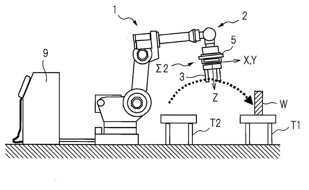
[0091] First, the first step will be described. Such as Figure 2A As shown, in a state where the hand 3 of the robot 1 is not holding the workpiece W, the hand 3 of the robot 1 is moved in the air without contacting peripheral equipment. The output of the force sensor 5 when the robot 1 is operated so that the posture of the wrist of the robot 1 does not change is represented by the following equation (4).
[0092] F1=Mh·R·(g+d 2 x / dt 2 +C(x, dx / dt)) (4)
[0093] Wherein, F1 is the force vector (detection value) detected by force sensor 5,
[0094] Mh is the mass ...
PUM
 Abstract
Description
Claims
Application Information
 - R&D
- Intellectual Property
- Life Sciences
- Materials
- Tech Scout
- Unparalleled Data Quality
- Higher Quality Content
- 60% Fewer Hallucinations
Browse by: Latest US Patents, China's latest patents, Technical Efficacy Thesaurus, Application Domain, Technology Topic, Popular Technical Reports.
© 2025 PatSnap. All rights reserved.Legal|Privacy policy|Modern Slavery Act Transparency Statement|Sitemap|About US| Contact US: help@patsnap.com


