
Piezoelectric vibratory energy harvester

A piezoelectric vibration and energy harvester technology, which is applied to generators/motors, piezoelectric effect/electrostrictive or magnetostrictive motors, electrical components, etc. , the performance of the energy harvester is degraded, etc., to achieve the effect of getting rid of the limitation of the resonance working state, improving the adaptability of the vibration source, and improving the transduction ability.

Active Publication Date: 2013-03-20
BEIHANG UNIV
View PDF4 Cites 16 Cited by
  • Summary
  • Abstract
  • Description
  • Claims
  • Application Information

AI Technical Summary

Problems solved by technology

However, since the stress of the constant-section cantilever energy harvester is relatively concentrated at the fixed end, when the mass of the mass block is too large, the fixed end of the constant-section cantilever energy harvester may break, and the quality of the mass block will be limited.
[0008] 3) When the frequency of the input vibration source deviates from its resonant frequency, the performance of the energy harvester drops sharply, and the adaptability to the vibration source is poor.
Using a flexible beam can free the energy harvester from the limitation of resonance work, but the flexible beam will not be able to support the mass block, so that the cantilever beam energy harvester with equal cross-section cannot work

Method used


Image

  • Piezoelectric vibratory energy harvester
  • Piezoelectric vibratory energy harvester
  • Piezoelectric vibratory energy harvester

Examples


Embodiment Construction

[0049] The present invention will be further described below in conjunction with the accompanying drawings and specific embodiments.

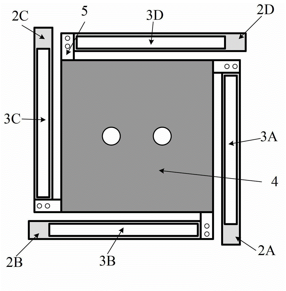
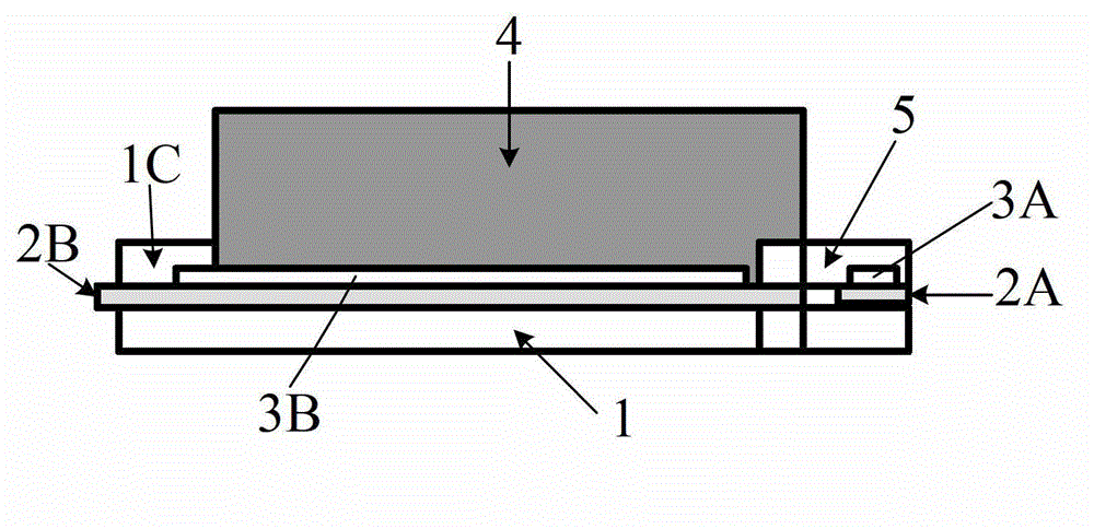
[0050] Such as figure 1 and figure 2As shown, the structure of the piezoelectric vibration energy harvester of the present invention is as follows in the order of marking: central installation structure 1, four-sided support beams 2A-2D, piezoelectric layers 3A-3D, central mass 4, and mounting arm splint 5. One end of the four support beams is clamped and installed by the installation arm of the central installation structure and the splint of the installation arm, the central mass block is installed on the square supporting plate of the central installation structure, and the piezoelectric layer is pasted on the surface of the support beam. There are lead-out electrodes on the upper and lower surfaces of the piezoelectric layer, which are used to output charges.

[0051] Such as image 3 Shown is a top view of the central mounting structur...


PUM


Abstract

The invention provides a piezoelectric vibratory energy harvester, which comprises a central mounting structure, four side support beams, piezoelectric layers and a central mass block, wherein the central mounting structure comprises square supporting plates and four centrosymmetric mounting arms; the four side support beams are fabricated by four rectangular metal beams with the same shape; mounting holes for mounting are formed at the two ends; the piezoelectric layers are formed by four piezoelectric ceramic sheets and pasted on upper surfaces of the four support beams; and the central mass block is superimposed by a plurality of metal sheets and mounted in an area formed by the square supporting plates of the central mounting structure. According to the energy harvester, the mass of the central mass block is increased, the structure layout is arranged reasonably, the strain distribution of the piezoelectric layers is improved, and the adaptability of the designed energy harvester to a vibration source is improved, so that the energy harvester has a better practical value.

Description

technical field [0001] The invention relates to a piezoelectric vibration energy harvester for collecting vibration mechanical energy in the environment and converting it into electric energy, in particular to a piezoelectric vibration energy harvester adopting a plurality of elastic beam structures. Background technique [0002] The current piezoelectric vibration energy harvester mainly adopts a single cantilever beam structure with equal cross-section. The piezoelectric vibration energy harvester is composed of a cantilever beam with one end fixed and the other free. The fixed end is connected to an environmental vibration source, and a mass block is installed at the free end. The mass block constitutes an energy harvesting structure. The transducer structure consists of a cantilever beam and a piezoelectric material pasted on the surface of the beam. [0003] There are the following problems in the cantilever beam type piezoelectric vibration energy harvester with equal...

Claims


Application Information

Patent Timeline
Patent Type & Authority Applications(China)
IPC IPC(8): H02N2/18
Inventor 袁梅李庆龙董韶鹏何涛鲍鹏宇庞卓
Owner BEIHANG UNIV
Learn More