
Water quality sensing device with automatic cleaning function

A sensing device and automatic cleaning technology, applied in the field of underwater sensing, can solve the problems of increasing relative cost, low cost, high cost, etc., and achieve the effect of avoiding continuous impact, reducing the impact of impurities, and being widely applicable

Inactive Publication Date: 2013-03-20
广东宸熙物联科技发展有限公司
View PDF5 Cites 22 Cited by
  • Summary
  • Abstract
  • Description
  • Claims
  • Application Information

AI Technical Summary

Problems solved by technology

[0003] In the past, technicians solved the above-mentioned problem of poor detection accuracy by manually scrubbing at regular intervals and replacing the sensing probe. However, it is obvious that this method is time-consuming, laborious, and costly, and it is difficult to realize industrialization and automation.
Later, some technicians developed a scheme to clean impurities on the surface of the sensor probe by ultrasonic waves, but it also has shortcomings; one is that the relative cost is greatly increased. For the original sensing device, the cost is not high. However, for The cost of the ultrasonic generator added to achieve ultrasonic cleaning is even greater than the cost of the original sensing device, and the price of the sensing device has nearly doubled, which is difficult to accept in practical industrial applications; the second is ultrasonic The impact on fishery, for some industrial and agricultural fields, such as fishery and other aquaculture industries, the propagation of ultrasonic waves in water may even cause fatal damage to some organisms, so ultrasonic cleaning solutions cannot be popularized and applied in these fields

Method used


Image

  • Water quality sensing device with automatic cleaning function
  • Water quality sensing device with automatic cleaning function
  • Water quality sensing device with automatic cleaning function

Examples


Embodiment Construction

[0029] The specific embodiment of the present invention will be further described below in conjunction with accompanying drawing:

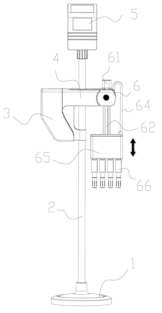
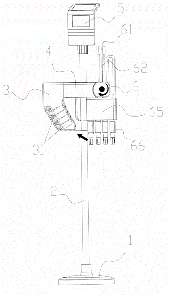
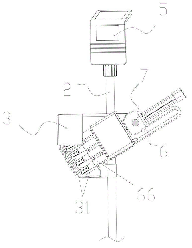
[0030] Such as Figures 1 to 3 As shown, a water quality sensing device with automatic cleaning function includes a vertical support part, an induction driving structure and a cleaning structure 3, and the cleaning structure 3 is fixed on the vertical support part.

[0031] In this embodiment, it also includes a horizontal support portion 4 perpendicular to the vertical support portion, the vertical support portion includes a support rod 2, the vertical support portion and the horizontal support portion 4 are used to fix and support the entire induction device, and The relative position of each component of the water quality sensing device is maintained.

[0032] The transverse support can be a separate transverse bar, or it can be an extension of the shell of the washing structure.

[0033] The support rod 2 is arranged vertically, and the late...


PUM


Abstract

The invention discloses a water quality sensing device with an automatic cleaning function. The water quality sensing device comprises a vertical supporting part, a cleaning structure and a sensing driving structure, wherein the sensing driving structure does reciprocating rotation around a rotating shaft; the sensing driving structure comprises a motor, a driving rod and a sensing probe; the driving rod does reciprocating movement under the driving of the motor; and when the sensing driving structure rotates to the cleaning structure, and the cleaning structure cleans the sensing probe. By the water quality sensing device, when a water body does not need to be detected, the driving rod takes the sensing probe out of water, so that the sensing probe cannot be influenced continuously by impurities in water and the speed the sensing probe is influenced by impurities can be slowed down greatly; when a water body needs to be detected, the driving rod puts the sensing probe into water; aims of flexible measurement and reduction of influence of impurities are fulfilled; and furthermore, when the probe needs to be cleaned, the sensing driving structure rotates around the rotating shaft, so that the probe is rotated to the cleaning structure to be scrubbed and cleaned.

Description

technical field [0001] The invention relates to the technical field of underwater sensing, in particular to a water quality sensing device with an automatic cleaning function. Background technique [0002] The underwater sensing device is mainly used to detect water body information, and obtain the desired water body information by analyzing various signals detected by various sensing probes. For the existing underwater sensing device, the sensing probe is soaked in water for a long time. Over time, impurities, microorganisms and calcified substances in the water will adhere to the surface of the sensing probe, which affects the water body information that should be detected. , making the detected water body information error gradually increase. [0003] In the past, technicians solved the above-mentioned problem of poor detection accuracy by manually scrubbing at regular intervals and replacing the sensing probe. However, it is obvious that this method is time-consuming, l...

Claims


Application Information

Patent Timeline
IPC IPC(8): G01N33/18B08B1/04
Inventor 梁永健刘盛理彭利民肖红生
Owner 广东宸熙物联科技发展有限公司
Learn More